Multi-level confocal conic surface secondary reflection unit light convergence method

A technology of secondary reflection and conic surface, applied in optics, condensers, optical components, etc., can solve the problems of unsuitable light convergence, small convergence ratio, and difficult to obtain converged light, etc., to achieve outstanding convergence effect, small divergence, easy to use Effects of use and installation

Inactive Publication Date: 2016-08-24
XIAN UNIV OF SCI & TECH
View PDF8 Cites 0 Cited by
  • Summary
  • Abstract
  • Description
  • Claims
  • Application Information

AI Technical Summary

Problems solved by technology

[0004] Among the combined light converging technologies that are currently used more often: the plane reflection method mostly adopts the reflection of multiple plane mirrors to obtain the converging light, such as CN101196612A, but its converging is relatively small; the optical lens method is limited by the size of the components, so it is not suitable for larger areas and Convergence of light over a longer distance; although the curved surface reflection method has involved the secondary reflection of the conical surface with confocal points, it mostly uses a single-stage form of two parabolic confocal combinations, such as patents CN101726843A, CN102062937A, and CN201917709U
None of the above methods can or is not easy to obtain converging light with extremely high luminous energy density and high brightness.

Method used


Image

  • Multi-level confocal conic surface secondary reflection unit light convergence method
  • Multi-level confocal conic surface secondary reflection unit light convergence method
  • Multi-level confocal conic surface secondary reflection unit light convergence method

Examples


Embodiment 1

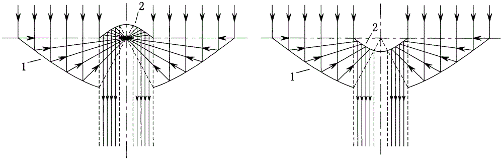
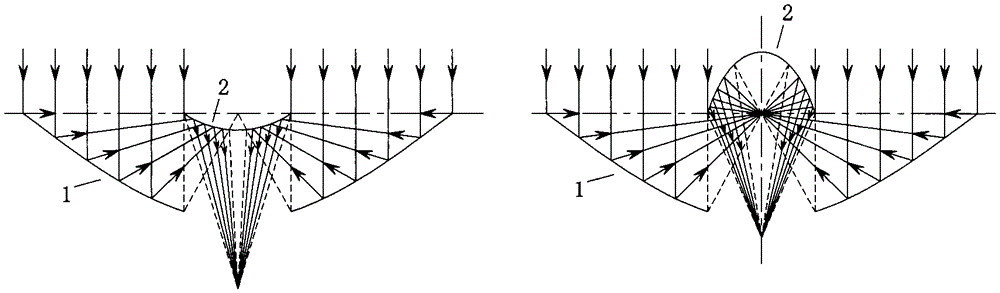
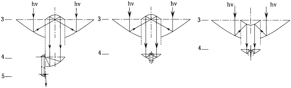
[0023] This embodiment is a two-level direct aggregation system, please refer to the attached image 3 In the right figure in the figure, the secondary reflective unit of the conical surface in the primary concentrating layer 3 is a confocal combination of parabola ~ parabola with the same opening direction, and the placement position of the secondary reflective unit in the secondary concentrating layer 4 utilizes The spatial shadow area of ​​the first-level parallel converging light, and adopts the attached figure 2 A secondary reflection element that produces intersecting converging rays is shown in . The entire converging system is installed in direct series with the first-level light-gathering layer 3 and the second-level light-gathering layer 4 .

[0024] In this embodiment, its action process is as follows: parallel light rays (low luminance light rays or low-density light energy) enter the secondary reflection unit of the first-level light-gathering layer 3, and are c...

Embodiment 2

[0026] This embodiment is a converging system that contains a multi-level concentrating layer and a plane reflective layer connected in tree form, please refer to the attached Figure 4 . This example includes three levels of light concentrating layers and two levels of planar reflection layers. The confocal conical surface secondary reflection unit in the first level of light concentrating layer 3 contains a parabola-parabola confocal combination of "opening directions are consistent and opposite". The first-level plane reflection layer 6 is composed of plane mirrors 7. The location of the secondary reflection unit in the second-level light-gathering layer 4 utilizes the spatial shadow area of ​​the light reflected by the first-level plane reflection layer 6. The second-level light-gathering layer 4 and the third-level light-gathering layer The secondary reflection units in layer 5 are all parabolic to parabola confocal combinations with “opposite opening directions”, and the...

Embodiment 3

[0029] This embodiment is a converging system that contains multi-level light concentrating layers, plane reflective layers, and light reflection channels connected in series. Please refer to the attached Figure 7 . This example contains three levels of light-gathering layers, two-level planar reflection layers, and one-level light reflection channel, and the secondary reflection of the co-focal conic surface in the first-level light-gathering layer 3, the second-level light-gathering layer 4, and the third-level light-gathering layer 5 The units are all parabolic to parabolic confocal combinations with "opposite opening directions". The primary plane reflection layer or light reflection channel layer 6 is composed of a plane mirror 7 and a light reflection channel 8. The placement position of the secondary reflection unit in the secondary light concentrating layer 4 is The spatial shadow area of ​​the light reflected by the first-level plane reflective layer 6 is defined, th...


PUM


Abstract

The present invention provides a method for obtaining high energy density and high brightness converged light via the convergence of multi-level series confocal conic surface secondary reflection units. The light convergence system of the method comprises multi-level light converging layers, and may also comprise planar reflecting layers or light-reflecting channels. The multi-level converging layers are directly connected in series, or the multi-level converging layers, the planar reflecting layers and the light-reflecting channels are connected in tree form in series, to form the light convergence system. The total convergence ratio of the light convergence system is sum of products of the convergence ratios of all levels of the secondary reflection units. Each level of the light converging layers is composed of a plurality of confocal conic surface secondary reflection units having special light converging effect; non-converging planar reflecting layers or light reflecting channel layers may be disposed among light converging layers, and are used for transferring the light into the next level converging layer or for output; and new incident light may be arranged among the multi-level light converging layers. The method can be widely used in a variety of occasions that need to enhance light signals, light energy density, and brightness, and will play an important role in the field of optics, solar energy utilization, etc.

Description

technical field [0001] The invention relates to a method for converging light, in particular to a method for obtaining converging light with high luminous energy density and high luminance by converging conical curved surface secondary reflection units with multi-stage series concentricity. Background technique [0002] Conics include parabolas, hyperbolas, and ellipses, and parabolas, hyperbolas, and ellipses have their own characteristic optical properties. The optical property of the parabola: the light parallel to the axis of symmetry is reflected by the rotating parabola (the surface generated by the parabola rotating around the axis), and all pass through the focus; otherwise, the light emitted from the focus becomes parallel after being reflected by the rotating parabola. The optical properties of the hyperbola: After the light emitted from one focus of the hyperbola is reflected by the hyperboloid of rotation (the rotating surface generated by the hyperbola rotating ...

Claims


Application Information

Patent Timeline
Patent Type & Authority Patents(China)
IPC IPC(8): G02B19/00G02B17/06G02B5/10
Inventor 张桂花
Owner XIAN UNIV OF SCI & TECH
Why Eureka
Try Eureka