Panoramic picture method based on hemisphere annular panoramic camera

A technology of panoramic lens and panoramic image, applied in the field of 360° panoramic vision

Inactive Publication Date: 2013-03-20
XIAN UNIV OF TECH
View PDF4 Cites 27 Cited by
  • Summary
  • Abstract
  • Description
  • Claims
  • Application Information

AI Technical Summary

Problems solved by technology

[0010] The purpose of the present invention is to provide a method for realizing a panoramic image based on a hemispherical annular panoramic lens, which can quickly correct the distortion of the image presented, and solve the problem of panoramic monitoring of a large field of view

Method used


Image

  • Panoramic picture method based on hemisphere annular panoramic camera
  • Panoramic picture method based on hemisphere annular panoramic camera
  • Panoramic picture method based on hemisphere annular panoramic camera

Examples


Embodiment Construction

[0033]The technical solution of the present invention will be described in detail below in conjunction with the accompanying drawings.

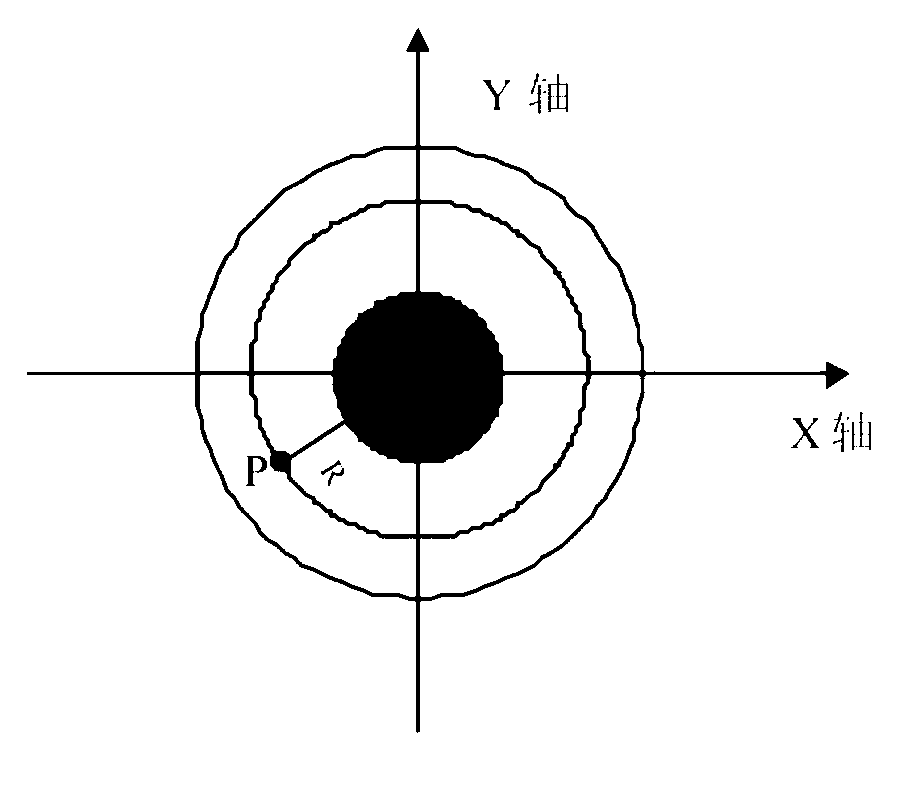
[0034] Due to its imaging principle, the hemispherical annular panoramic lens compresses all the scenes in the entire field of view into a circular zone, so the problem to be solved is how to design an algorithm to "expand" the information in this circular zone, that is, Find a mapping relationship between the distorted image and the standard image.

[0035] In order to visualize this ring belt, please refer to figure 1 As shown, the central black area is the blind area. For the convenience of calculation, this circular zone is moved to the Cartesian coordinate system, the horizontal axis is the x-axis, and the vertical axis is the y-axis. figure 1 The radius R shown in is the distance from the point in the figure to the origin of the coordinates, which can be determined by Calculated.

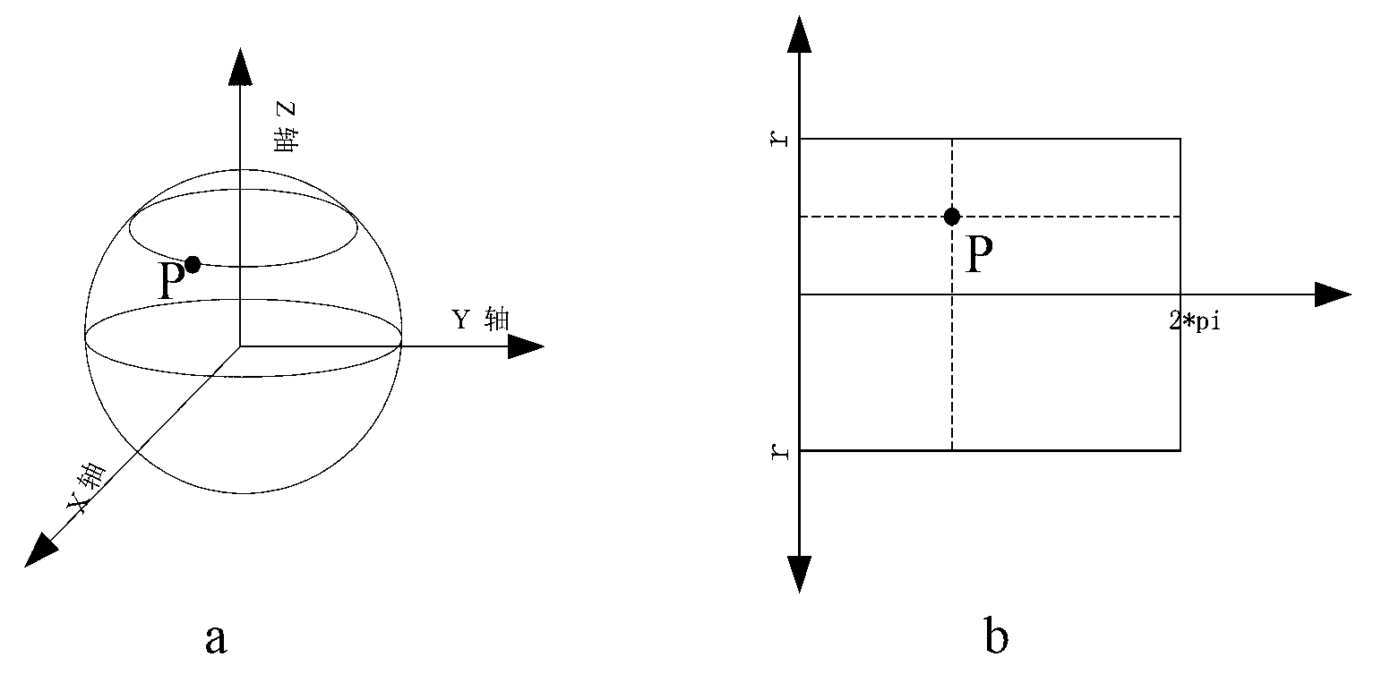
[0036] Since the shape of the hemispherical panoram...


PUM


Abstract

The invention discloses a panoramic picture method based on a hemisphere annular panoramic camera which includes the following steps: firstly, dividing an original image into four small areas, transforming coordinates and forming an isosceles trapezoid image; secondly, stretching the isosceles trapezoid image into a rectangular image through a bilinear transformation method. When one area is processed, corresponding relationship of coordinates can be directly applied to the rest three areas. Finally the four areas are connected from head to tail in sequence. A strip-shaped 360 DEG panoramic picture is obtained and regarded as a rectangular image capable of being accepted by human being and processed by a computer. A certain breakthrough on rapidity of algorithm is achieved. The aim is to achieve effect of real-time monitoring. Image quality is good enough to satisfy general video monitoring requirement.

Description

technical field [0001] The invention belongs to the technical field of 360° panoramic vision, and relates to a method for realizing a panoramic image based on a hemispherical annular panoramic lens, in particular to methods such as image affine transformation. Background technique [0002] Today, video surveillance systems have been widely used in various fields. Cars, aircraft, and submarines are gradually equipped with video surveillance systems. However, traditional cameras have very limited fields of view due to lens constraints. In order to obtain a large field of view, often It is necessary to add multiple sensors. As a result, the cost increases a lot. Furthermore, in order to fuse the images acquired by multiple sensors into a panoramic image, multiple splicing is required, which is complex and time-consuming, and often cannot achieve the effect of real-time monitoring, which makes its function Big discount. [0003] Due to its short focal length and large field of...

Claims


Application Information

Patent Timeline
Patent Type & Authority Applications(China)
IPC IPC(8): G06T5/50G06T3/40
Inventor 刘龙王攀李军
Owner XIAN UNIV OF TECH
Why Eureka
Try Eureka