Heat sealing equipment and method for solar cell module

A technology of solar modules and sealing equipment, applied in the direction of electrical components, semiconductor devices, sustainable manufacturing/processing, etc., can solve the problem of double-sided tape sealing and adhesion, unsatisfactory solar modules, shortening production and turnover Time and other issues, to achieve the effect of low cost, fast speed and long service life

Active Publication Date: 2013-03-20
DSM SUNSHINE SOLAR TECH (SUZHOU) CO LTD
View PDF11 Cites 0 Cited by
  • Summary
  • Abstract
  • Description
  • Claims
  • Application Information

AI Technical Summary

Problems solved by technology

The double-sided tape does not need to be cured, which greatly shortens the production and turnaround time, but the sealing and adhesion of the double-sided tape do not meet the requirements of existing solar modules, and the aging resistance is poor, and it is not suitable for long-term outdoor work, so this method Not ideal for sealing solar modules

Method used


Image

  • Heat sealing equipment and method for solar cell module
  • Heat sealing equipment and method for solar cell module
  • Heat sealing equipment and method for solar cell module

Examples


Embodiment 1

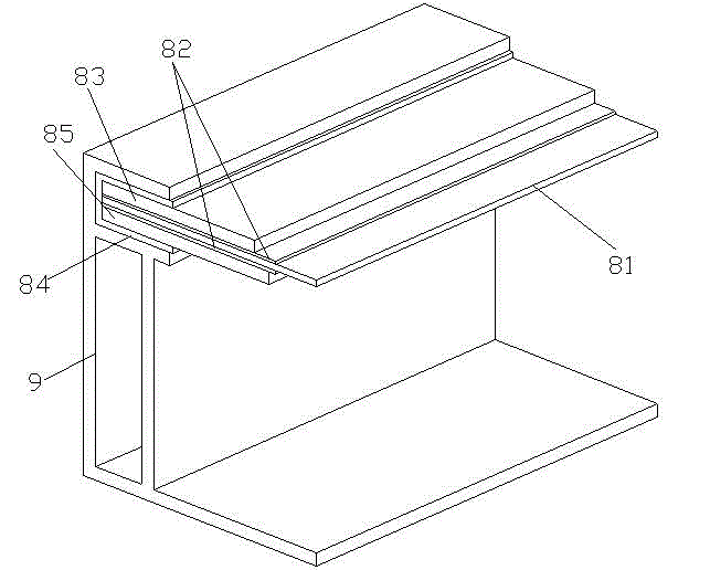
[0036] Embodiment 1: as Figure 4 As shown, a single-layer heating and sealing device for solar modules includes a layer of heating units, the heating unit includes a conveying positioning mechanism 4 extending laterally on the lower layer, an annular heating mechanism 6 located on the upper layer, and a heating element located on the conveying positioning mechanism 4 and heating The jacking mechanism 5 in the middle part of mechanism 6. The conveying positioning mechanism 4, the heating mechanism 6 and the jacking mechanism 5 are all arranged on the upper end of the rectangular parallelepiped frame frame 3. The top of the frame 3 is provided with a guardrail 31 with a central opening, and a corner of the top is provided with a man-machine interface 1. The lower end is provided with electric control cabinet 2.

[0037] Such as Figure 5As shown, the conveying positioning mechanism 4 includes a roller conveyor whose conveying direction is transverse, and two front baffles 41 ...

Embodiment 2

[0049] Embodiment 2: as Figure 8 As shown, a double-layer heating and sealing equipment for solar modules includes a square main frame 16, an inner frame 28 arranged inside the main frame 16 through a lifting mechanism, and upper and lower layers of heating elements arranged in the inner frame 28. Units 22, 24. The structure of each layer of heating unit is the same as that of the single layer of heating unit in Example 1. The lifting mechanism includes two driving screw rods 18 extending longitudinally between the upper heating unit 22 and the lower heating unit 24 and a lifting driver 26 connected to the driving screw rods 18 and extending transversely.

[0050] When the heating and sealing time of a solar module is longer than the time for a conveyor line to transport a solar module, it is necessary to use a heating and sealing device with multiple heating units to heat the solar module. For example, the speed at which the conveyor line transports the solar modules is 50...


PUM


Abstract

The invention relates to heat sealing equipment and a method for a solar cell module. The equipment is characterized in that the heat sealing equipment comprises at least one heat unit, wherein each heat unit comprises a conveying location mechanism positioned at the lower layer and extending transversely, an annular heat mechanism positioned at the upper layer, and a climbing mechanism arranged in the middle of the conveying location mechanism and the heat mechanism. The equipment and the method are high in heat sealing speed, convenient to operate, high in efficiency, and suitable for large-scale automatic production, a sealing material is low in cost and convenient to transport, the obtained solar cell module is good in sealing effect and long in service life, requirements of the solar cell module on long operation are completely met, and the production efficiency of the solar cell module manufacturing industry can be improved greatly. The heat sealing equipment can be used individually and used in a flow conveying line.

Description

technical field [0001] The invention relates to the field of sealing of solar modules, in particular to a device and method for heating and sealing. Background technique [0002] With the rapid development of solar cell modules (hereinafter referred to as solar modules) and the continuous innovation of its technology, the products are gradually developing towards high reliability and high power generation performance. Nowadays, the continuous working life of solar modules is required to be more than 25 years. Therefore, after the solar modules are laminated to form a laminated panel, it is necessary to seal the edge of the laminated panel and install a frame. Good edge sealing materials and processes can achieve Sealing, bonding, shock resistance, moisture barrier and other functions, so as to ensure the normal operation and performance of solar modules in harsh natural environments. [0003] The bonding and sealing of the laminated panel and the frame in the solar cell mod...

Claims


Application Information

Patent Timeline
Patent Type & Authority Applications(China)
IPC IPC(8): H01L31/18
CPCY02P70/50
Inventor 韩东流
Owner DSM SUNSHINE SOLAR TECH (SUZHOU) CO LTD
Why Eureka
Try Eureka