Multi-cell zero-forcing interference suppression method
An interference suppression, multi-cell technology, applied in baseband system components, shaping networks in transmitters/receivers, etc., can solve the problem that the interference of multi-cell mobile communication systems cannot be completely eliminated, and is not suitable for large-scale application in actual communication systems. , the complexity of the tedious algorithm, etc., to achieve the effect of easy implementation, suppression of interference, and simple algorithm
- Summary
- Abstract
- Description
- Claims
- Application Information
AI Technical Summary
Problems solved by technology
Method used
Image
Examples
Embodiment 1
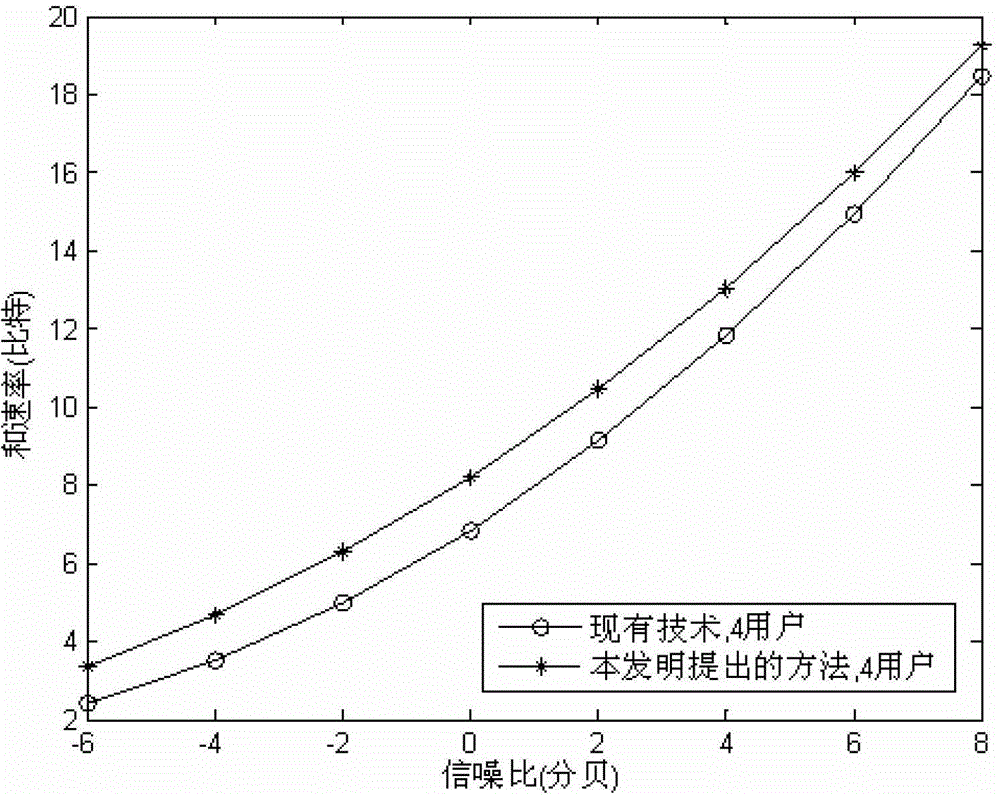
[0040] In this embodiment, taking the 4-cell cooperative system as an example, the channel fading factor β between the base station and the user is ik Both are set to 0.8, and the SNR of the system is defined as the average SNR of each receiving antenna at the user end, namely: where P represents the transmit power of each base station, Represents the noise variance; because each subcarrier is generally allocated to one user in the cell at a certain moment, the number of users can be set to be equal to the number of cells; the antenna pairs between the base station and the user are (8, 2), respectively.
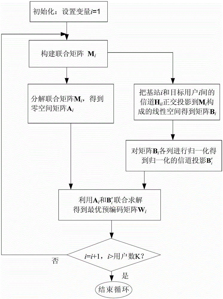
[0041] A multi-cell zero-forcing interference suppression method as shown in Figure 1 in the flow chart mainly includes steps:
[0042] S1. Extract all channel information of the multi-cell communication system; in this embodiment, users send pilot signals to all base stations, and the base stations estimate and obtain all channel information according to the pilot signals...
Embodiment 2
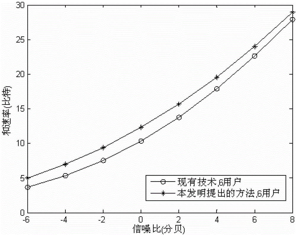
[0072] In this embodiment, the coordinated system of 6 cells is taken as an example, and the channel fading factor β between the base station and the user is set ik Both are set to 0.6, and the antenna pairs between the base station and the user are (12, 2) respectively; other settings and operation steps are the same as those in Embodiment 1.
[0073] image 3 It is a performance comparison chart of the system and rate obtained by the method of the present invention and the technical solution based on singular value decomposition under the above circumstances; it can be seen that the method of the present invention is obviously better than the technical solution based on singular value decomposition, especially at low signal-to-noise ratio The gain is greater.
[0074] In summary, the present invention first uses the obtained channel information set at the base station to construct a joint matrix, uses singular value decomposition of the matrix to obtain the eigenvector set ...
PUM
 Abstract
Description
Claims
Application Information
 - R&D
- Intellectual Property
- Life Sciences
- Materials
- Tech Scout
- Unparalleled Data Quality
- Higher Quality Content
- 60% Fewer Hallucinations
Browse by: Latest US Patents, China's latest patents, Technical Efficacy Thesaurus, Application Domain, Technology Topic, Popular Technical Reports.
© 2025 PatSnap. All rights reserved.Legal|Privacy policy|Modern Slavery Act Transparency Statement|Sitemap|About US| Contact US: help@patsnap.com


