Distillation process and multi-column heat-integrated distillation system

A distillation system and distillation tower technology, applied in the field of distillation systems, can solve problems such as low energy efficiency, achieve high energy efficiency, and reduce the number of effects

Inactive Publication Date: 2013-03-20
SAUDI BASIC IND CORP SA
View PDF4 Cites 2 Cited by
  • Summary
  • Abstract
  • Description
  • Claims
  • Application Information

AI Technical Summary

Problems solved by technology

Prior art methods use multiple fired reboilers, or separate thermal oil systems that are less energy efficient and / or more expensive than using the multi-column heat integrated distillation system described of

Method used


Image

  • Distillation process and multi-column heat-integrated distillation system
  • Distillation process and multi-column heat-integrated distillation system
  • Distillation process and multi-column heat-integrated distillation system

Examples


example 2

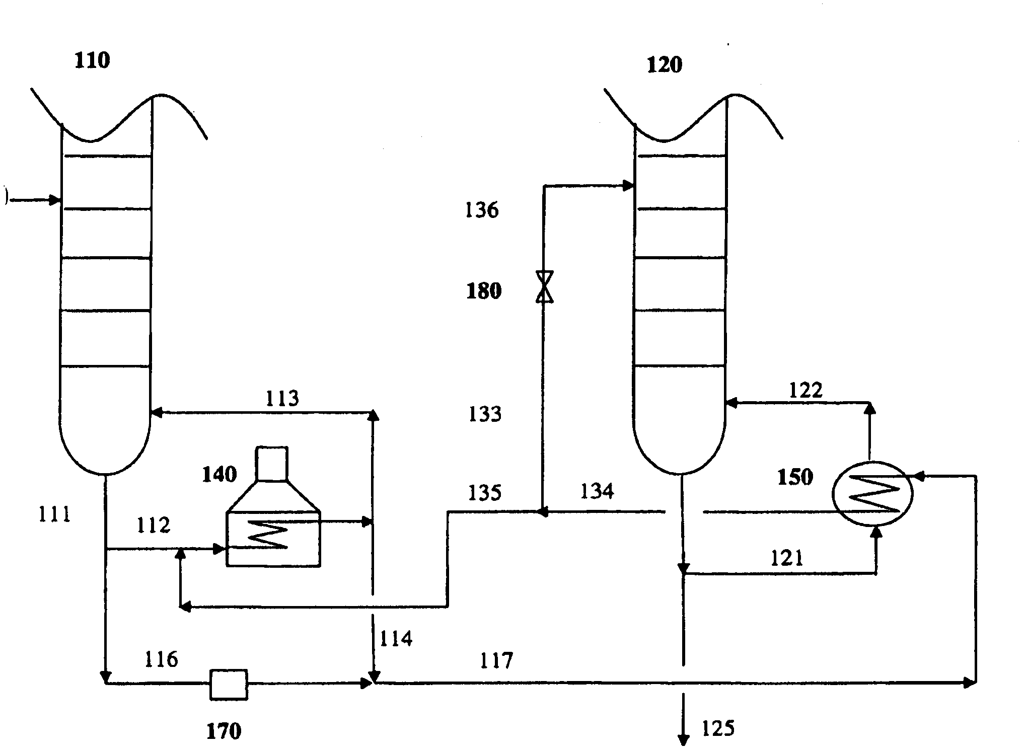
[0058] For the setup used in Comparative Experiment 1, the initial feed flow to the second column was completely stopped and the feed heat exchanger was removed. Instead, use a portion of the second reboiler outlet stream (i.e. from the common stream) as the second column feed and pass it through an expansion valve to further adjust its pressure and reduce its pressure before entering the second column as feed. temperature. The balance stream from the second reboiler was fed upstream of the first fired heater of the first (xylene) column. This situation is related to figure 1 The scheme shown in is similar; using a pump but without stream 114 from the first reboiler. The distillation operating parameters after the above changes of the present invention are given in Table 1.

[0059] These results clearly show that, for Example 2, the calculated fired reboiler energy load required to reheat the second reboiler balance stream back to its original temperature (i.e. 314°C), min...

example 3

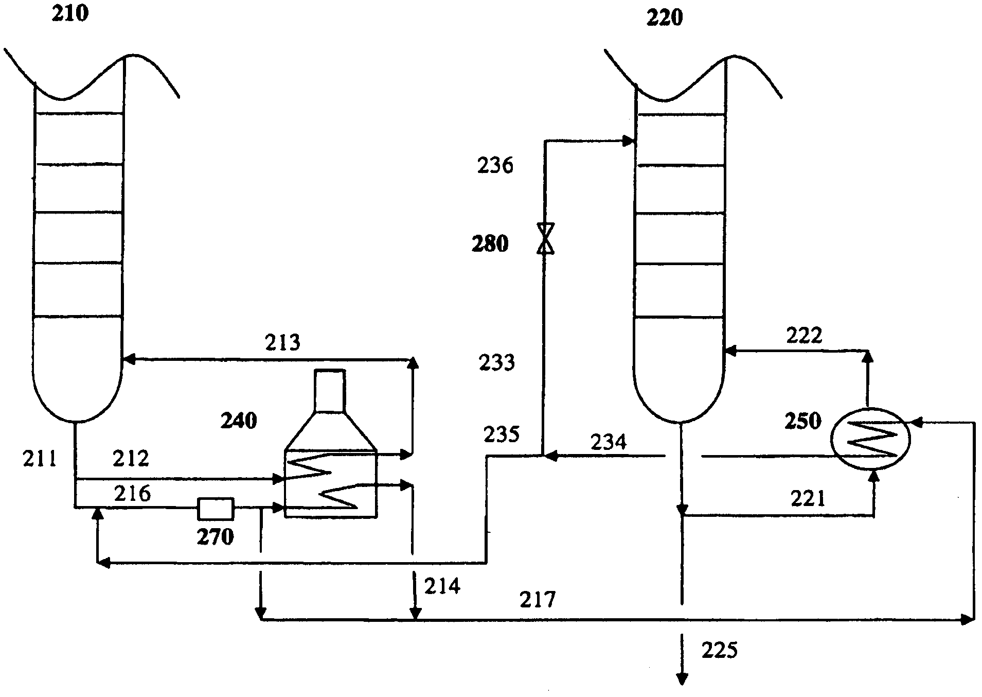
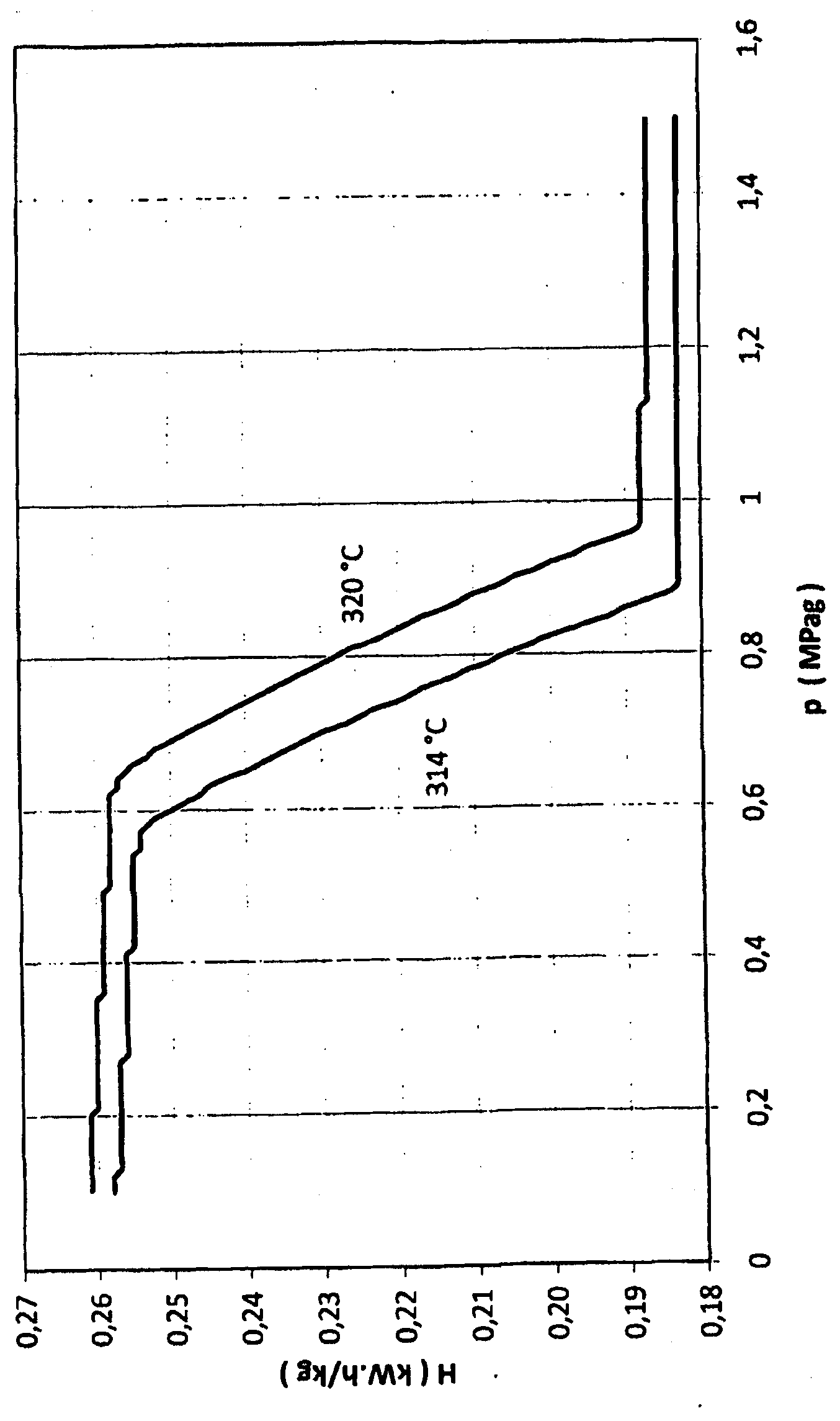
[0064] refer to image 3, it can be seen that although an inlet pressure of 2.1 MPag lies in the flat section of the enthalpy change for a stream at a temperature of 314°C, it is possible - see Example 2 - by using the reboiler outlet stream as the column feed and the A downstream expansion valve was used to further cool the feed and regulate its pressure, saving energy in heat load and improving the separation efficiency of the column. It also shows that further improvements can be made, for example by minimizing the reboiler flow back to the upstream fired reboiler. Example 3 represents simulation results based on Example 2 and using commercially available software. In Example 3, the stream pressure was reduced below the xylene bottoms pressure, which can actually be achieved using a pressure reducing valve, with additional heating to the initial feed inlet temperature (e.g. figure 1 structure shown using stream 114 or figure 2 structure shown utilizing stream 214).

[...


PUM

PropertyMeasurementUnit
boiling pointaaaaaaaaaa

Abstract

The invention relates to a process for separating a multi-component feed mixture in a distillation system comprising a first distillation column having a first fired reboiler, and at least a second distillation column having a second heat-exchange reboiler, comprising the steps of a) introducing the feed mixture to the first column, and separating into at least a first top and a first bottom product; b) taking part of the first bottom product for providing heat to the second reboiler as a utility stream; and c) feeding part of said utility stream after heat-exchange as main feed to the second column for further separation. This process allows significant energy savings, by reduction of the amount of external heat required for the fired reboiler and omission of a conventionally used heat-exhanger. The invention also relates to such distillation system suitable for separating a multi-component mixture with the process of the invention.

Description

technical field [0001] The present invention relates to a method for separating a multicomponent feed mixture in a distillation system comprising at least two distillation columns each having a reboiler system. More particularly, the present invention relates to a method for separating a multicomponent feed mixture in a distillation system comprising a first distillation column having a first combustion reboiler, and a second heat exchange reboiler at least one second distillation column. [0002] The invention also relates to a distillation system comprising a first distillation column with a first combustion reboiler, and at least one second distillation column with a second heat exchange reboiler, which system is suitable for separating Multi-component mixture. Background technique [0003] Distillation is one of the most widely used separation techniques in the chemical industry. Standard distillation typically introduces a multicomponent feed (which is a mixture of t...

Claims


Application Information

Patent Timeline
Patent Type & Authority Applications(China)
IPC IPC(8): B01D3/00B01D3/14B01D3/32B01D3/42C07C7/00C07C15/067
CPCC07C7/04B01D3/322B01D3/007B01D3/42B01D3/143Y02P20/10Y02P20/50C07C15/08B01D3/4283B01D3/4288B01D3/4294
Inventor M·S·阿布德尔格哈尼
Owner SAUDI BASIC IND CORP SA
Why Eureka
Try Eureka