
Steel tube flaring and punching device

A technology for punching devices and steel pipes, which is applied in the direction of feeding devices, positioning devices, storage devices, etc., can solve problems such as low efficiency, safety hazards, and complicated procedures, and achieve improved work efficiency, maintenance of integrity, and high mechanical strength Effect

Inactive Publication Date: 2013-03-27
青岛豪德博尔实业有限公司
View PDF4 Cites 15 Cited by
  • Summary
  • Abstract
  • Description
  • Claims
  • Application Information

AI Technical Summary

Problems solved by technology

At present, the flaring and punching of pipe fittings are carried out separately, and the flaring machine and the punching machine are operated separately. The process is complicated and the efficiency is low; in the process of punching after reaming, the steel pipe needs to be transported. Handling is often carried by hand or hanging by driving. During the hanging process, the steel pipe needs to be bound with cables. Because there are no bolt holes on the surface of the steel pipe, the binding is not firm, which is likely to cause safety hazards. Punching, it is easy to make the connection line of the punching holes at both ends not parallel to the axis, and it is easy to cause safety hazards during the subsequent handling and hanging process

Method used


Image

  • Steel tube flaring and punching device
  • Steel tube flaring and punching device
  • Steel tube flaring and punching device

Examples


Embodiment Construction

[0021] The substantive features and advantages of the present invention will be further described below in conjunction with examples, but the present invention is not limited to the listed embodiments.

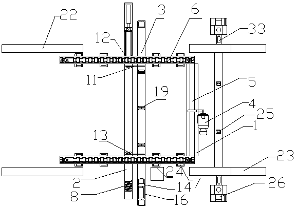
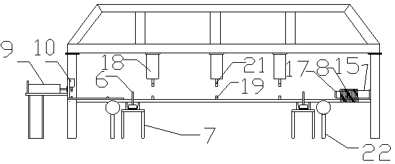
[0022] like Figure 1-6 As shown, the steel pipe flaring and punching device includes a first support 1, a second support 2, a third support 3 between the first support 1 and the second support 2, and the second support 2 is equipped with Heating device, the third support 3 is provided with a flaring machine, and the first support 1 is provided with a steel pipe transmission mechanism, which is used to transport the steel pipe on the loading rack 22 to the heating device for heating and then transport the steel pipe to the flaring machine Expand the mouth, and transport the steel pipe after the expansion to two punching machines 26 arranged on both sides of the blanking frame 23 for punching at the same time. The material rack 23 is arranged on the right side of the first sup...


PUM


Abstract

The invention discloses a steel tube flaring and punching device. The device comprises a first support, a second support and a third support arranged between the first support and the second support; wherein a feeding frame is arranged on one side of the first support and a blanking frame is arranged on one side of the second support; a steel tube heating device is arranged on the second support and a steel tube flaring machine is arranged on the third support; and a steel tube conveying mechanism is arranged on the first support and used for conveying steel tubes on the feeding frame to the heating device for heating, then conveying the steel tubes to the flaring machine for flaring, and conveying the steel tubes to two punching machines for simultaneous punching, wherein the two punching machines are oppositely arranged on two sides of the blanking frame. According to the adoption of the technical scheme, the steel tubes can be flared and punched after being heated, the steel tubes processed by the device not only are high in mechanical strength and long in service life, but also the pipe fitting integrity is maintained, welding is not needed, and the bell-and-spigot joint operation efficiency of the steel tubes is improved greatly.

Description

technical field [0001] The invention relates to a pipe fitting processing equipment, in particular to a steel pipe flaring and punching device. Background technique [0002] The pipe fittings used for cable threading generally adopt the socket connection method. The socket connection requires that the diameters of the two ends of the pipe fittings used for cable threading are different. Generally, a steel pipe with a large diameter and small length is welded at one end of the pipe fittings used for cable threading. Connection, this The connection method not only destroys the integrity of the pipe fittings used for cable threading, but also requires welding, which is very troublesome and inefficient. In order to solve the above problems, at present, when the cable is threaded, the threading pipe is usually flared and the pipe fitting is punched to facilitate threading. At present, the flaring and punching of pipe fittings are carried out separately, and the flaring machine a...

Claims


Application Information

Patent Timeline
Patent Type & Authority Applications(China)
IPC IPC(8): B21D41/02B21D28/28B21D43/00B21D43/02B21D37/16
Inventor 陈建仪策清董国强
Owner 青岛豪德博尔实业有限公司
Learn More