Tool of low-pressure hub and heat treatment method for forming low-pressure hub

A low-pressure wheel and tooling technology, used in heat treatment furnaces, heat treatment equipment, workpiece clamping devices, etc., can solve the problems of lack of tooling, difficulty in determining the phase angle of the wheel disc, etc., to reduce labor intensity, clear steps, and high success rate. Effect

Inactive Publication Date: 2013-03-27
HARBIN TURBINE
View PDF6 Cites 3 Cited by
  • Summary
  • Abstract
  • Description
  • Claims
  • Application Information

AI Technical Summary

Problems solved by technology

[0003] The purpose of the present invention is to provide a tooling for low-pressure hubs and a heat treatment method for forming low-pressure hubs, so as to solve the problem that the current low-pressure hubs of gas turbines are assembled, and it is difficult to determine the phase angle between the discs and other problems due to the fact that the discs at all levels are in a rotating state. The problem of lack of tooling when heat treatment after welding

Method used


Image

  • Tool of low-pressure hub and heat treatment method for forming low-pressure hub
  • Tool of low-pressure hub and heat treatment method for forming low-pressure hub
  • Tool of low-pressure hub and heat treatment method for forming low-pressure hub

Examples


specific Embodiment approach 1

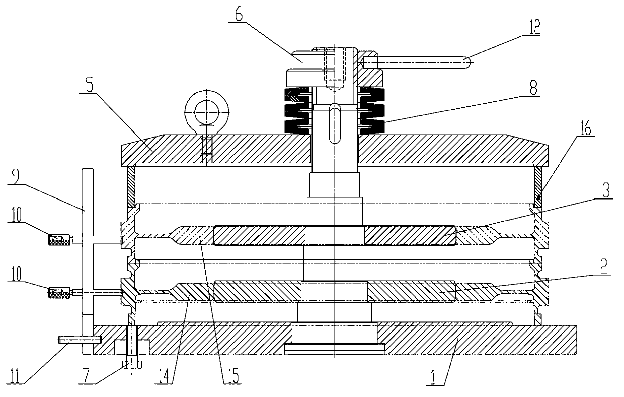
[0019] Specific implementation mode one: combine figure 1 , Figure 4 , Figure 5 , Figure 6 , Figure 7 , Figure 8 , Figure 9 and Figure 10 Describe this embodiment, the tooling described in this embodiment is the assembly tooling of a primary and secondary roulette, and the assembly tooling of the primary and secondary roulette includes a mold 1, a first mandrel body 2, and a second mandrel body 3 , a gland 5, a nut 6, a bolt 7, an elastic device 8, a support plate 9, a secondary press-fit workpiece 16 and two positioning pins 10, the mold 1 includes a chassis 1-1 and a mandrel 1-2 , the chassis 1-1 is arranged horizontally, the mandrel 1-2 is arranged vertically, the mandrel 1-2 is a stepped shaft body, and the large diameter end of the chassis 1-1 and the mandrel 1-2 is fixedly connected Made as a whole, the mandrel 1-2 is sequentially fitted with the first mandrel body 2, the second mandrel body 3 and the gland 5 from the large-diameter end to the small-diamete...

specific Embodiment approach 2

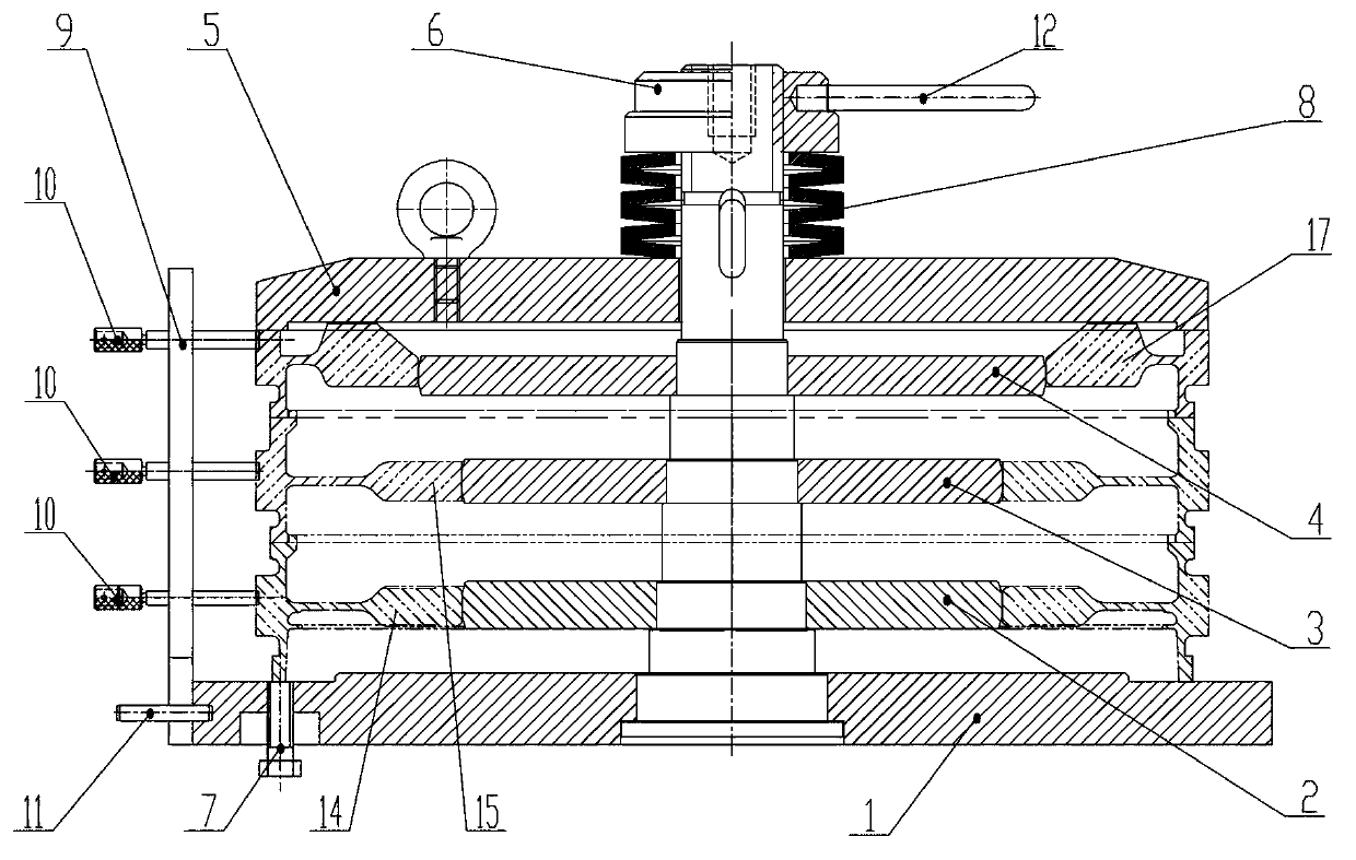
[0020] Specific implementation mode two: combination figure 2 , Figure 4 , Figure 5 , Figure 6 , Figure 7 , Figure 8 , Figure 9 and Figure 10Describe this embodiment. The tooling described in this embodiment is the assembly tooling of the second and third stage roulettes, and the assembly tooling of the second and third stage roulettes includes a mold 1, a first mandrel body 2, and a second mandrel body 3 , the third mandrel body 4, the gland 5, the nut 6, the bolt 7, the elastic device 8, the support plate 9 and three positioning pins 10, the mold 1 includes a chassis 1-1 and a mandrel 1-2 , the chassis 1-1 is arranged horizontally, the mandrel 1-2 is a vertically arranged stepped shaft body, and the large diameter end of the mandrel 1-2 passes through the through hole on the chassis 1-1 and the chassis 1-1 is fixedly connected as a whole, and the mandrel 1-2 is sequentially fitted with the first mandrel body 2, the second mandrel body 3, the third mandrel body...

specific Embodiment approach 3

[0021] Specific implementation mode three: combination figure 1 , figure 2 , Figure 4 , Figure 5 , Figure 6 , Figure 7 , Figure 8 , Figure 9 and Figure 10 This embodiment will be described. In this embodiment, the elastic device 8 is a belleville spring. Belleville springs can achieve better utility model effects. Other compositions and connections are the same as those in Embodiment 1 or 2.


PUM


Abstract

The invention discloses a tool of a low-pressure hub and a heat treatment method for forming a low-pressure hub, which relates to a tool and a heat treatment method thereof, and aims at solving the problems that the phase angle between wheel discs is difficult to determine since the wheel discs of all levels are in a rotating state when in assembly of a low-pressure hub of an existing gas turbine and a tool for heat treatment is unavailable after welding. The tool of the wheel discs is an assembly tool for the first-level and second-level wheel discs, an assembly tool for the second-level and third-level wheel discs or a heat treatment tool. The heat treatment method of a low-pressure hub comprises the following steps of: (I) the mounting and welding works of the first-level wheel disc and the second-level wheel disc; (II) the mounting work of the third-level wheel disc and the welding work of the third-level wheel disc and the second-level wheel disc; and (III) the heat treatment work of the low-pressure hub. The tool disclosed by the invention has reasonable structure design, the steps of the method are simple, the application range is wide, and the feasibility is high. The tool and the heat treatment method disclosed by the invention are applied to the assembly work and the heat treatment work of the low-pressure hub.

Description

technical field [0001] The invention relates to a tooling and a heat treatment method thereof, in particular to a tooling for a low-pressure wheel hub and a heat treatment method for forming the low-pressure wheel hub. Background technique [0002] Gas turbine is composed of compressor, equipment for heating working medium (such as combustion chamber), turbine, control system and auxiliary equipment. motivation. The parts of the gas turbine have complex structures and are difficult to process. Basically, the processing of each part must be guaranteed by tooling. The low-pressure hub of the gas turbine unit is composed of three-stage discs. After the discs are finished, the three-stage discs need to be connected into low-pressure hubs by welding, and then the welded low-pressure hubs are heat-treated, and then installed on the rotor mandrel. superior. The difficulty in the current assembly process is that there is a phase angle between the roulette and the roulette, and th...

Claims


Application Information

Patent Timeline
Patent Type & Authority Applications(China)
IPC IPC(8): B23K37/04B25B11/00C21D9/34
Inventor 詹春辉太秀滨李岩姚青文杨广利董生权
Owner HARBIN TURBINE
Why Eureka
Try Eureka