
Spherical surface machining method

A spherical surface processing and to-be-processed technology, applied in the field of mechanical parts processing, can solve the problems of high profile requirements, difficult repairs, and high processing costs, and achieve the effects of simplifying processing procedures, reducing processing costs, and improving processing efficiency.

Active Publication Date: 2015-07-01
WUHAN MARINE MACHINERY PLANT
View PDF8 Cites 2 Cited by
  • Summary
  • Abstract
  • Description
  • Claims
  • Application Information

AI Technical Summary

Problems solved by technology

[0005] When grinding the spherical surface of the workpiece to be processed, the precision of the CNC grinding and the profile of the grinding wheel are high. At the same time, it is difficult to repair the grinding wheel after wear, which will lead to high processing costs.

Method used


Image

  • Spherical surface machining method
  • Spherical surface machining method
  • Spherical surface machining method

Examples


Embodiment

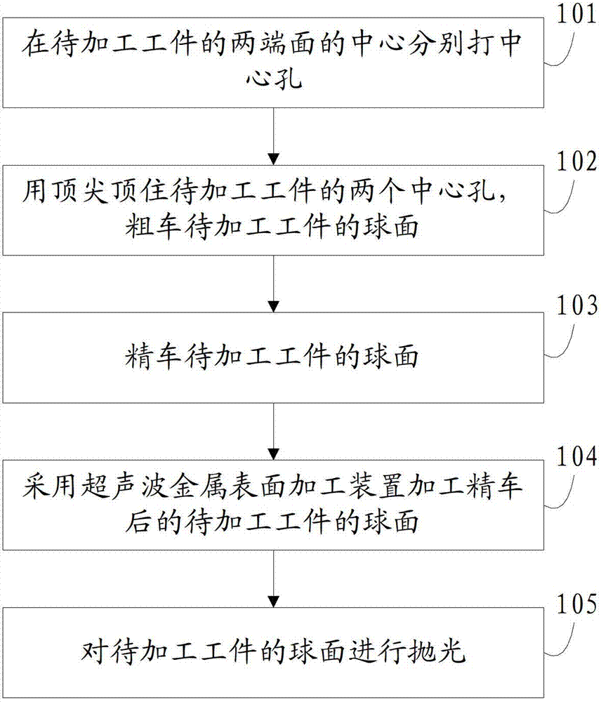
[0038] Combine below figure 1 The method is described in detail as figure 1 As shown, the method includes:

[0039] Step 101: Drilling center holes at the centers of the two end surfaces of the workpiece to be processed, the above-mentioned end surfaces being perpendicular to the center line of the workpiece to be processed.

[0040] Place the workpiece to be processed on the rotary table of the boring machine, fix the workpiece to be processed, and punch a center hole in the center of the end face.

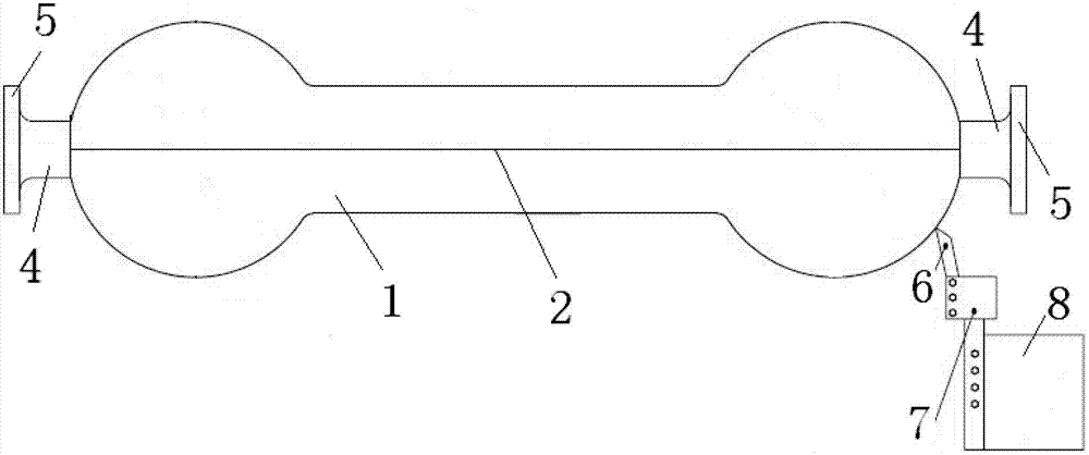
[0041] Take the processing of the two spherical surfaces of the hinge shaft as an example, see figure 2 , draw a cross line on the end face of the hinge shaft, and the intersection point of the cross line is the center of the end face. Specifically, draw the waistline 2 of the hinge shaft 1 first, and lead the waistline 2 to the two end surfaces 3 , and then draw a vertical line on the straight line leading to the end surfaces 3 .

[0042] Before marking, use vernier caliper...


PUM


Abstract

The invention discloses a spherical surface machining method belonging to the technical field of machine part machining. The method comprises the following steps of sequentially carrying out rough turning, finish turning, grinding and polishing on a spherical surface of a workpiece to be machined by using a numerical control machine tool, wherein the grinding step is implemented as follows: the finish-turned spherical surface of the workpiece to be machined is machined by using an ultrasonic metal surface machining device which is arranged on the numerical control machine tool. According to the spherical surface machining method, the finished-turned spherical surface of the workpiece to be machined is machined by using the ultrasonic metal surface machining device which replaces a numerical control grinder in the prior art, and therefore, the precision and the smooth finish of the spherical surface of the workpiece to be machined are ensured, and meanwhile, the machining process is simplified, the used equipment is reduced, the machining efficiency is improved, and the machining cost is lowered.

Description

technical field [0001] The invention relates to the technical field of mechanical parts processing, in particular to a spherical surface processing method. Background technique [0002] Spherical structures are usually used in some mechanical parts, such as hinge shafts. Usually, in the processing requirements of these parts, the requirements for the accuracy, contour and surface roughness of the spherical surface are high. [0003] In the existing spherical surface processing method, the spherical surface of the workpiece to be processed is mainly used for rough turning and finishing turning with a CNC lathe, and then the spherical surface of the workpiece to be processed is ground with a CNC grinding wheel, and finally the spherical surface is polished. [0004] In the process of realizing the present invention, the inventor finds that there are at least the following problems in the prior art: [0005] When grinding the spherical surface of the workpiece to be processed,...

Claims


Application Information

Patent Timeline
Patent Type & Authority Patents(China)
IPC IPC(8): B23P15/00B23P9/02B23B1/00
Inventor 宋玉军由国静唐长平张怀斌
Owner WUHAN MARINE MACHINERY PLANT
Learn More