
Pole restraint device

A restraint device and rod-type technology, which is applied to the restraint field of aircraft test pieces, can solve problems such as the inability to guarantee effective displacement, and achieve the effect of reliable and effective restraint and reliable horizontal restraint.

Active Publication Date: 2013-03-27
CHINA AIRPLANT STRENGTH RES INST
View PDF2 Cites 10 Cited by
  • Summary
  • Abstract
  • Description
  • Claims
  • Application Information

AI Technical Summary

Problems solved by technology

[0003] When the feedback load at the constraint point is large, it is necessary to apply a large pretightening force on the two soft constraints to ensure the effectiveness of the constraint in the test. Real assessment; when the position control actuator is used as the constraint point, the actuator cannot guarantee effective displacement in the non-test state (the actuator has no oil pressure state), and the attitude of the testing machine will be adjusted first after pressurization. May cause out-of-tolerance protection of other loading points

Method used


Image

  • Pole restraint device
  • Pole restraint device

Examples


Embodiment Construction

[0016] Below in conjunction with accompanying drawing and embodiment the present invention will be further described:

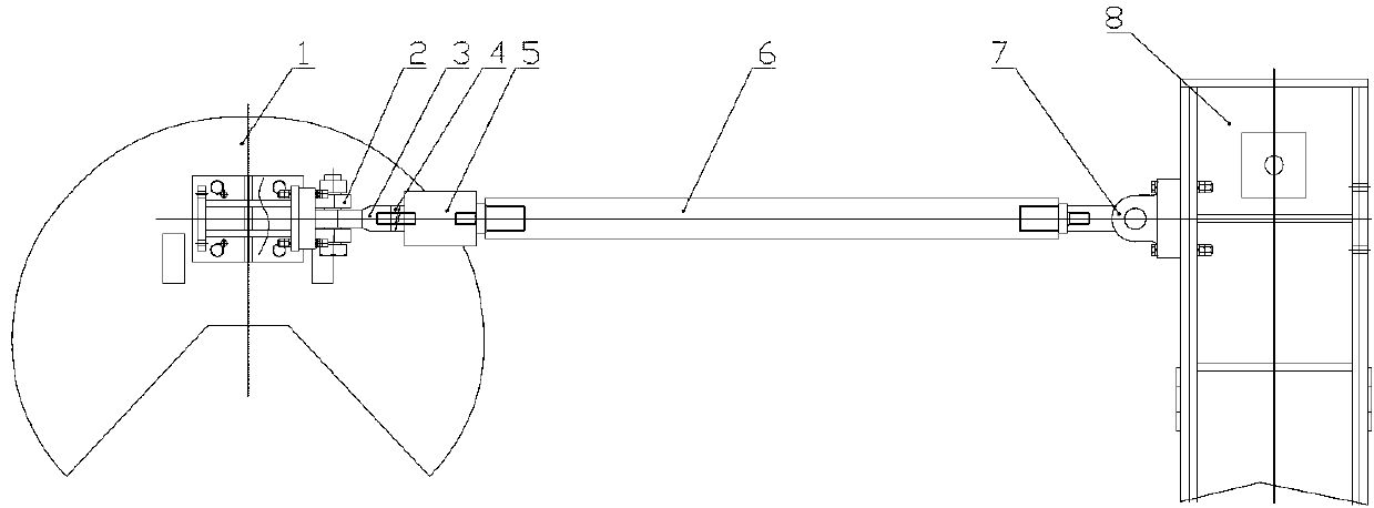
[0017] Such as figure 1 As shown, the brace-type restraint device of the present invention includes a double ear joint 2 , a connecting screw 3 , a helical pad 4 , a load sensor 5 , a dummy actuator 6 , and an actuator base 7 . The double-ear joint 2 is fixed on the restraint part of the test piece, and is connected with the connecting screw 3 in a hinged manner, so as to provide lateral (or heading) degrees of freedom for the entire restraint device. The screw pad is installed on the threaded connection between the load sensor 5 and the dummy moving cylinder 6 to eliminate the gap of the threaded connection. The load sensor 5 is connected with the control system for feeding back the load of the constraint point. The actuator base 7 is fixed on the column 8, and is connected with the dummy actuator 6 in a hinged manner, so as to provide the vertical freedom ...


PUM


Abstract

The invention belongs to an aircraft test piece constraint technology, and relates to a pole restraint device. The pole restraint device comprises a binaural joint, a connecting screw rod, a spiral pad, a load sensor, and a false actuating cylinder, wherein the binaural joint is fixed on a test piece constraint part and connected with the connecting screw rod in a hinge manner; the spiral pad is added to the threaded connection part between the load sensor and the false actuating cylinder, and the load sensor is connected with the control system. The pole restraint device disclosed by the invention can regulate the gesture of a testing machine by regulating the telescopic length of a connecting steel tube of the false actuating cylinder; and constraint of a 'two-force bar' structure in rigid connection under a shutdown state is still reliable and valid. Therefore, the existing testing equipment is effectively utilized, and reliable horizontal constraint is also achieved.

Description

technical field [0001] The invention belongs to the restraint technology of aircraft test pieces, and relates to a brace type restraint device. Background technique [0002] In the static / fatigue test of the full-scale aircraft structure, the constraints of the test machine are statically determinate constraints. Generally, three vertical constraints are selected, and the other three constraints are horizontal constraints (including heading constraints and lateral constraints). Half of the vertical restraint methods are crowbar or suspension restraint, while the horizontal restraint is joint, pulley, chute and column restraint, two-way differential soft restraint or position control cylinder position control restraint. Adopt the form of joints, pulleys, chute and columns, not restrict the vertical displacement of the aircraft, and restrain the aircraft heading and lateral displacement. Due to the gap between the pulley and the chute, the failure of the heading and lateral co...

Claims


Application Information

Patent Timeline
IPC IPC(8): B64F5/00B64F5/60
Inventor 王征夏峰张建锋王刚郑建军朱亚辉
Owner CHINA AIRPLANT STRENGTH RES INST
Learn More