Eccentric swing type speed reduction device

A technology of reduction gear and eccentric swing, applied in the direction of transmission, transmission parts, gear transmission, etc., can solve the problem of cost and other problems, and achieve the effect of high lubricity

Active Publication Date: 2013-03-27
SUMITOMO HEAVY IND LTD
View PDF7 Cites 7 Cited by
  • Summary
  • Abstract
  • Description
  • Claims
  • Application Information

AI Technical Summary

Problems solved by technology

So as a result there are

Method used


Image

  • Eccentric swing type speed reduction device
  • Eccentric swing type speed reduction device
  • Eccentric swing type speed reduction device

Examples


Example Embodiment

[0022] Hereinafter, an example of an embodiment of the present invention will be described in detail based on the drawings.

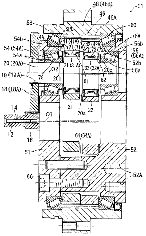
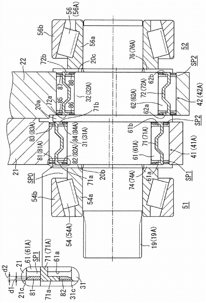
[0023] figure 1 It is a cross-sectional view showing a configuration example of an eccentric swing type reduction gear G1 called a so-called sorting type according to an example of the embodiment of the present invention. figure 2 It is a cross-sectional view of its main parts.

[0024] Hereinafter, the description will start from the schematic structure of the reduction gear G1.

[0025] The input shaft 12 is connected to a motor (not shown) via a key 14. A pinion 16 is formed at the front end of the input shaft 12. The pinion gear 16 meshes with three distribution gears 18 (18A to 18C: only 18A in the figure). Each distribution gear 18 is fixed to three eccentric body shafts 20 (20A to 20C: only 20A shown) by splines 19 (19A to 19C: only 19A shown). According to this structure, by rotating the input shaft 12, the three eccentric body shafts 20 are synch...


PUM


Abstract

The invention provides an eccentric swing type speed reduction device, which can better maintain lubricity of an eccentric body bearing without increase of cost. In the speed reduction device, first and second rollers (61, 62) form first and second eccentric body bearings (41, 42) disposed between first and second eccentric bodies (31, 32), and first and second external gears (21, 22), furthermore, spaces between the first and second eccentric bodies (31, 32), and first and second external gears (21, 22) are set to be first and second sealing spaces (SP1, SP2), lubricant is sealed in the sealing spaces (SP1, SP2), and the first and second rollers (61, 62) are disposed.

Description

technical field [0001] The invention relates to an eccentric swing type reduction gear. Background technique [0002] Patent Document 1 discloses an eccentric oscillating type reduction gear transmission. [0003] The reduction gear transmission includes an external gear that swings by an eccentric body, and an internal gear that internally engages while the external gear swings. The difference in the number of teeth between the internal teeth of the internal gear and the external teeth of the external gear is set to "1", and the relative rotation of the internal gear and the external gear due to the difference in the number of teeth is taken out when the external gear swings inside the internal gear. [0004] An eccentric body bearing is disposed between the eccentric body and the external gear. Eccentric body bearings are composed of rollers (rolling elements) and cages that support the rollers, and do not have dedicated inner and outer rings. Therefore, a washer (stopp...

Claims


Application Information

Patent Timeline
IPC IPC(8): F16H1/32F16H57/04F16H57/029F16H57/023
CPCF16C33/7893F16C33/7889F16H1/32F16H2001/323
Inventor 石川哲三芳贺卓志津庆刚
Owner SUMITOMO HEAVY IND LTD
Why Eureka
Try Eureka