Insulated piercing wire clip

A technology of insulation puncture and clamp, applied in the direction of needle tip/slotted plate contact, clamping/spring connection, electrical components, etc. used to penetrate insulating wire/cable core wire, which can solve the problem of unreasonable internal structure and use Problems such as short service life and unstable performance, etc., achieve the effect of simple pressure resistance, good sealing, and variable pressure resistance

Inactive Publication Date: 2013-03-27
YUEQING KEYI ELECTRIC GROUP
View PDF7 Cites 3 Cited by
  • Summary
  • Abstract
  • Description
  • Claims
  • Application Information

AI Technical Summary

Problems solved by technology

[0002] The insulation puncture clamp is mainly composed of an insulating shell, a puncture blade, a waterproof rubber pad, and a torque bolt. When connecting a cable branch, insert the branch cable into the branch cap and determine the branch position of the main line, and then use a socket wrench to tighten the screw on the clamp. Torque nut, with the tightening of the torque nut, the upper and lower insulators with piercing blades hidden in the clamp gradually close together. At

Method used


Image

  • Insulated piercing wire clip
  • Insulated piercing wire clip
  • Insulated piercing wire clip

Examples


Embodiment Construction

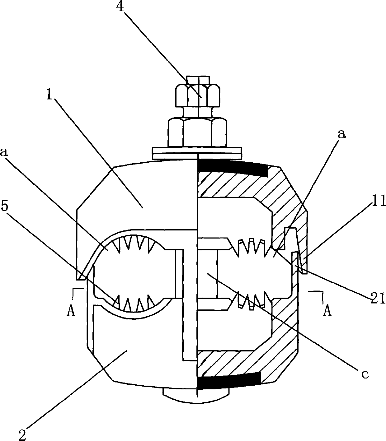
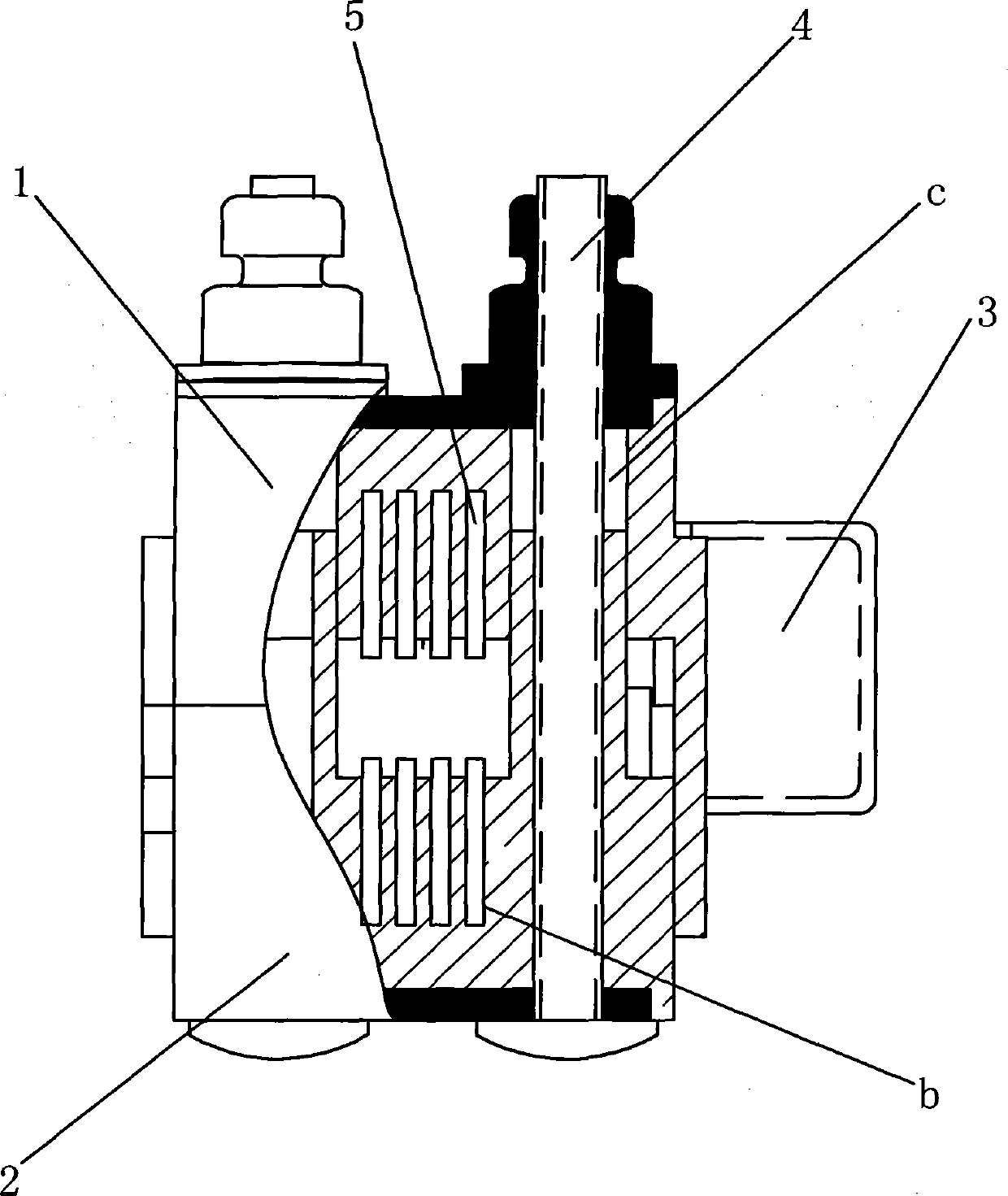
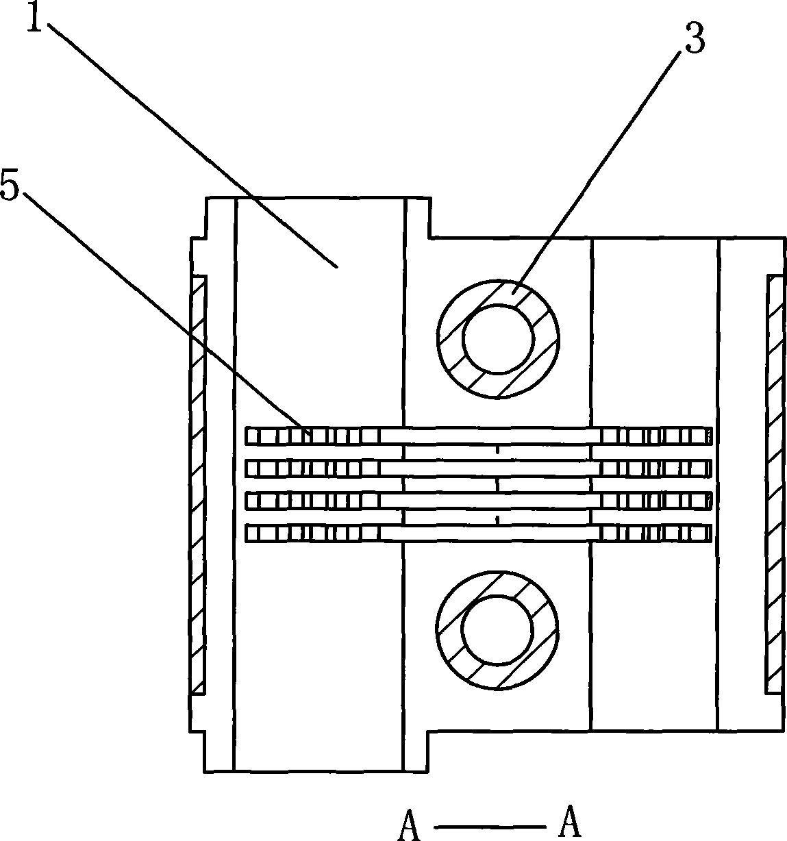
[0017] like Figure 1-3 As shown, the specific embodiment of the present invention is an insulating puncture clamp, including an insulating upper cover 1, an insulating lower seat 2, a plastic case cover 3, two torque bolts 4 and four sets of piercing blades 5, an insulating upper cover 1 and an insulating lower Two semicircular through-holes a are arranged horizontally on the seat 2, and four sets of mounting grooves b are respectively arranged on the insulating upper cover 1 and the insulating lower seat 2 in the longitudinal direction, and eight sets of piercing blades 5 are fixedly arranged on the insulating upper cover 1 respectively. In the eight sets of installation grooves b of the insulating lower seat 2, a bolt mounting platform c is provided in the middle part of the insulating upper cover 1 and the insulating lower seat 2, and the piercing blade 5 is fixedly arranged between the two bolt installing platforms c. The cover 1 and the insulating lower seat 2 are fixedl...


PUM


Abstract

The invention relates to an insulated piercing wire clip, which comprises an insulated upper cover, an insulated lower base, a plastic shell cover, a plurality of groups of piercing blades and torque screw bolts, wherein two semicircle through holes are formed on the insulated upper cover and the insulated lower base transversely and correspondingly; a plurality of groups of mounting grooves are formed on the insulated upper cover and the insulated lower base longitudinally and correspondingly; the groups of piercing blades are respectively fixedly arranged inside the groups of mounting grooves of the insulated upper cover and the insulated lower base; screw bolt mounting tables are arranged among each mounting grooves; the groups of mounting grooves are close to each other side by side and longitudinally arranged in the middle part of the insulated upper cover and the insulated lower base; the groups of piercing blades are respectively fixedly arranged inside the groups of mounting grooves; and the screw bolt mounting tables are fixedly arranged on both sides of the groups of piercing blades. The distances between the piercing blades and the edges of the insulated upper cover and the insulated lower base are larger, and the distances between the piercing blades and the torque screw bolts are larger, so that the distance between climbing arcs becomes larger and the pressure endurance capability of product is also higher.

Description

technical field [0001] The invention relates to a connection device for electric power, in particular to an insulation piercing clip. Background technique [0002] The insulation puncture clamp is mainly composed of an insulating shell, a puncture blade, a waterproof rubber pad, and a torque bolt. When connecting a cable branch, insert the branch cable into the branch cap and determine the branch position of the main line, and then use a socket wrench to tighten the screw on the clamp. Torque nut, with the tightening of the torque nut, the upper and lower insulators with piercing blades hidden in the clamp gradually close together. At the same time, the arc-shaped sealing rubber pad wrapped around the piercing blade gradually clings to the cable insulation layer, and the piercing blade also begins to pierce the cable. The insulating layer and the metal conductor realize the conduction, but the internal structure of the insulation piercing clamps currently on the market is no...

Claims


Application Information

Patent Timeline
IPC IPC(8): H01R11/09H01R4/44H01R4/24
Inventor 刘树良
Owner YUEQING KEYI ELECTRIC GROUP
Why Eureka
Try Eureka