Motor with magnetic rotor

A magnetic pole rotor and rotor technology, applied in the direction of magnetic circuit rotating parts, magnetic circuit static parts, magnetic circuit shape/style/structure, etc., can solve the problems of affecting the service life of the motor, poor heat dissipation, etc., and achieve economical processing Materials, enhanced heat dissipation, and weight reduction effects

Inactive Publication Date: 2013-03-27
无锡金阳电机有限公司
View PDF2 Cites 3 Cited by
  • Summary
  • Abstract
  • Description
  • Claims
  • Application Information

AI Technical Summary

Problems solved by technology

The change of the magnetic field in the motor will generate heat. The current rotor punches are mostly ring-shaped, which has poor heat dissipation and affects the service life of the motor.

Method used


Image

  • Motor with magnetic rotor

Examples


Embodiment Construction

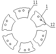
[0010] Such as figure 1 As shown, the motor with a magnetic pole rotor described in the embodiment of the present invention includes a rotor punch 1, the rotor punch 1 is set in an arc shape, and six rotor punches form a ring; on the outer arc surface of the arc There are slots 11 for winding wire groups, and a through hole 12 is provided on the plane between the two slots 11 . Optionally, an even number of rotor punches is used to form a corresponding integer number of magnetic pole pairs.

[0011] The stator of the motor with a magnetic pole rotor is configured as a permanent magnet magnetic pole structure, which is sheathed on the outer periphery of the rotor to provide magnetic field power and drive the rotor to run.

[0012] The through holes are provided on the rotor punching sheet to enhance the heat dissipation effect, reduce the weight and save materials at the same time.


PUM


Abstract

The invention discloses a motor with a magnetic rotor. The motor comprises arc-shaped rotor sheets. Even number of rotor sheets form a circle. Tooth grooves for winding wires are arranged on the outer arc face of the arc. Through holes are arranged on the side face between two tooth grooves. By the through holes disposed on the rotor sheets or stator sheets, radiation performance is enhanced, machining materials are saved, and weight is reduced. In addition, the multi-sheet combining rotor or stator structure facilitates radiation.

Description

technical field [0001] The invention is an electric machine with a pole rotor. Background technique [0002] Current motors with pole rotors generate force from the interaction of magnetic fields generated by both the rotor and the stator, at least one of which is electrodynamically varied to drive the rotor in rotation. The change of the magnetic field in the motor will generate heat. Most of the current rotor punches are ring-shaped, and the heat dissipation is not good, which affects the service life of the motor. Contents of the invention [0003] The purpose of the present invention is to provide a motor with a magnetic pole rotor to solve the problem of heat dissipation of the rotor in the motor. [0004] The purpose of the present invention is achieved through the following technical solutions: a motor with a magnetic pole rotor, including a rotor punch, the rotor punch is set in an arc shape, and an even number of rotor punches form a ring; The arc surface is pro...

Claims


Application Information

Patent Timeline
Patent Type & Authority Applications(China)
IPC IPC(8): H02K1/26H02K1/17
Inventor 陈彬生
Owner 无锡金阳电机有限公司
Why Eureka
Try Eureka