
Motor

A technology of insulating sleeve and rotor core, applied in the shape/style/structure of winding insulation, etc., can solve problems such as insulation

Inactive Publication Date: 2013-03-27
无锡金阳电机有限公司
View PDF6 Cites 5 Cited by
  • Summary
  • Abstract
  • Description
  • Claims
  • Application Information

AI Technical Summary

Problems solved by technology

[0003] The purpose of the present invention is to provide a motor that solves the problem of insulation between the rotor and its mounting shaft

Method used


Image

  • Motor
  • Motor

Examples


Embodiment Construction

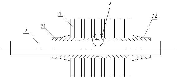
[0012] Such as figure 1 As shown, the motor according to the embodiment of the present invention includes a rotor composed of a shaft 2, a rotor core 1 mounted on it, and two insulating sleeves 31 and 32, and the two insulating sleeves 31 and 32 are sleeved on On the shaft 2, the rotor core 1 is sheathed on two insulating sleeves; one ends of the two insulating sleeves are correspondingly connected.

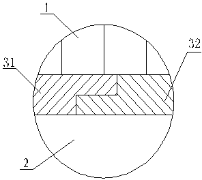
[0013] figure 1 The insulating sleeves 31 and 32 shown in , extend out of the rotor core 1 respectively, that is, the assembly degree of the two insulating sleeves is greater than that of the rotor core, and the protruding part extends radially along the rotor core 1 to form a flange; At the same time, the end faces of the corresponding ends connected by the two insulating sleeves are set to be gradient matching, such as figure 2 Partial enlargement is shown.

[0014] In order to further enhance the connection strength of the two insulating sleeves, a conventional snap-fit ​​...


PUM


Abstract

The invention discloses a motor comprising a shaft and a rotor iron core mounted on the shaft. The motor is characterized by further comprising two insulation sleeves, the two insulation sleeves are sleeved on the shaft, the rotor iron core is sleeved on the two insulation sleeves, and one ends of the two insulation sleeves are correspondingly connected. The insulation sleeves are additionally arranged between the rotor iron core and the mounting shaft and function in insulating the same. The two insulation sleeves are convenient to adjust and mount.

Description

technical field [0001] The invention is a motor. Background technique [0002] At present, the power of the motor comes from the magnetic field between the stator and the rotor, and the rotor is driven to rotate to drive the load. A wound rotor in an electric motor consists of a shaft and a rotor core mounted on the shaft, around which wire is wound to form an armature. The rotor core is generally press-fitted on the shaft. Although this structure can provide a strong connection force, it is difficult to ensure the insulation between the winding on the rotor and the shaft in some environments with high safety requirements. Contents of the invention [0003] The purpose of the present invention is to provide a motor that solves the problem of insulation between the rotor and its mounting shaft. [0004] The purpose of the present invention is achieved through the following technical solutions: a motor, including a rotor composed of a shaft and a rotor core mounted on it, ...

Claims


Application Information

Patent Timeline
IPC IPC(8): H02K3/34
Inventor 陈彬生
Owner 无锡金阳电机有限公司
Learn More