Motor control device
A motor control and motor technology, applied in the direction of control systems, current controllers, vector control systems, etc., can solve problems such as different and difficult system applications
- Summary
- Abstract
- Description
- Claims
- Application Information
AI Technical Summary
Problems solved by technology
Method used
Image

Examples
no. 1 approach
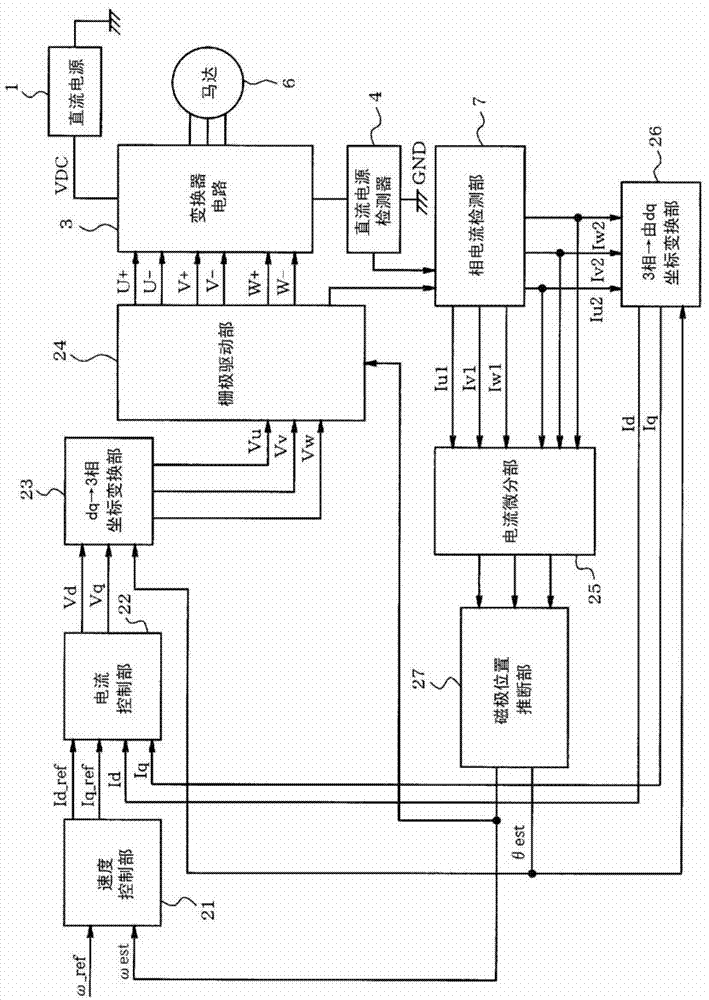
[0030] Below, refer to Figure 1 to Figure 9 The first embodiment will be described. figure 1 It is a functional block diagram showing the configuration of the motor control device. The speed control unit 21 performs proportional integral (PI) or proportional integral derivative (PID) on the difference between the speed command value ω_ref given from the outside and the speed ωest of the motor 6 estimated by the magnetic pole position estimation unit 27 described later. control, thereby generating current command values Id_ref and Iq_ref, and outputting these current command values to the current control unit 22 . In addition, when the motor 6 is a permanent magnet motor such as a brushless DC motor and performs full excitation operation, the current command value Id_ref of the d-axis is set to zero.
[0031] The current control unit 22, like the speed control unit 21, performs PI or PI on the difference between the above-mentioned current command value and the d-axis cu...
no. 2 approach
[0061] Figure 10 2nd Embodiment is shown, the same code|symbol is attached|subjected to the same part as 1st Embodiment, and description is abbreviate|omitted, and a different part is demonstrated below. The second embodiment shows an example in which the duty of the three-phase PWM pattern is adjusted by the duty increase / decrease unit 11 incorporated in the PWM signal generation unit 9 . In the estimation method of the present embodiment, the larger the current differential value is, the higher the estimation accuracy of the magnetic pole position is, and the larger the S / N ratio is. However, on the other hand, when the current differential value becomes too large, noise corresponding to the PWM carrier frequency and electromagnetic noise increase.
[0062] Such as Figure 10 As shown, when passing Figure 5 When the load of all phases is uniformly reduced as shown in the graph, the high-frequency current amplitude (current differential value) decreases, and when adjuste...
no. 3 approach
[0068] Figure 11 to Figure 13 It is a figure explaining 3rd Embodiment, and only the part which differs from 1st Embodiment is demonstrated below. Such as Figure 11 As shown in the functional block diagram of , in the third embodiment, the magnetic pole position estimation unit 27 of the first embodiment is used as the first magnetic pole position estimation unit 27, and a second magnetic pole position estimation unit 41 (second magnetic pole position estimation unit 41) is further provided. inference unit, induced voltage detection unit). The second magnetic pole position estimating unit 41 calculates the induced voltage based on electrical characteristics such as the d-axis voltage Vd, the q-axis voltage Vq, the d-axis current Id, the q-axis current Iq, and the inductance and resistance of the winding of the motor 6, and calculates the induced voltage based on the electrical characteristics such as the inductance and resistance value of the winding of the motor 6. The ma...
PUM
 Abstract
Description
Claims
Application Information