laryngoscope

A laryngoscope and blade technology, which is applied in the field of blade self-destruction devices and laryngoscopes, can solve the problems of increasing the risk of cross-infection and disease of patients, producing harmful substances, the blade being unable to withstand high temperature or corrosion of disinfectant, etc. The effect of germ cross-transmission and infection

Active Publication Date: 2014-10-22
SHENZHEN CENTURY WEI CHUANG MEDICAL TECH CO LTD
View PDF7 Cites 0 Cited by
  • Summary
  • Abstract
  • Description
  • Claims
  • Application Information

AI Technical Summary

Problems solved by technology

[0004] The problem is that although the blades used on the laryngoscope are generally replaceable disposable blades, some users will reuse the disposable blades after simple high-temperature disinfection in order to save costs or troubles, but The material of the existing disposable leaves cannot withstand high temperature or corrosion by disinfectant, and may produce harmful substances after high temperature disinfection, thus causing harm to medical staff and patients
Some users even simply wipe the leaves and use them again, which greatly increases the risk of cross-infection of patients

Method used


Image

  • laryngoscope
  • laryngoscope
  • laryngoscope

Examples


Embodiment 1

[0028] The blade self-destruction device is arranged on the handle connected with the blade bracket, including: a self-destruction lever, a self-destruction groove and a blade fixing part for fixing the blade;

[0029] One end of the self-destruct lever is rotationally connected to the handle through a rotating shaft, and the other end is free;

[0030] The blade fixing part is arranged on the self-destruct lever, one end connected with the handle in rotation;

[0031] The self-destruction groove is arranged on the handle, between the position connected with the self-destruction rod and the position connected with the blade support.

[0032] Compared with the prior art, the blade self-destruction device provided by the present invention is provided with a self-destruction rod and a self-destruction groove which can destroy used blades and prevent reuse, and one end of the self-destruction rod is connected to the The handle turns to connect and the other end is free.

[0033]...

Embodiment 2

[0042] Embodiment 2: as Figure 2-Figure 5 As shown, in order to further provide more beneficial effects, the following embodiments are provided.

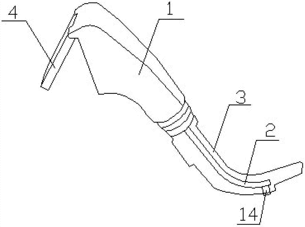
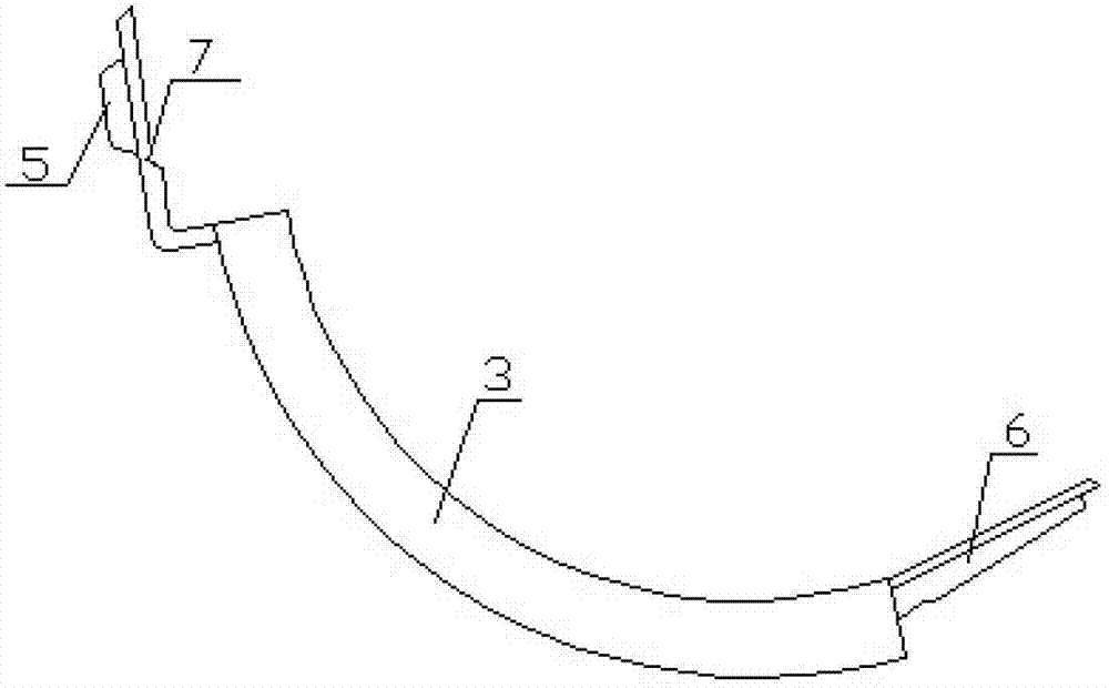
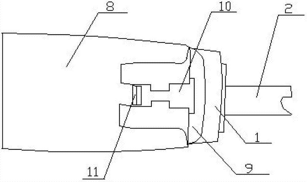
[0043] The blade self-destruction device is arranged on the handle 1 connected with the blade bracket 2, including: a self-destruction lever 8, a self-destruction groove 9 and a blade fixing part 10 for fixing the blade 3;

[0044] One end of the self-destruct lever 8 is rotationally connected with the handle 1 through a rotating shaft, and the other end is free;

[0045] The blade fixing part 10 is arranged on the self-destruct lever 8, one end connected with the handle 1 in rotation;

[0046]The self-destruct slot 9 is provided on the handle 1 between the position connected with the self-destruct lever 8 and the position connected with the blade support 2 .

[0047] Compared with the prior art, the blade self-destruction device provided by the present invention is provided with a self-destruction rod 8 and a self-destruction gr...


PUM


Abstract

The invention relates to the field of medical equipment, in particular to a blade self-destruct device and a laryngoscope, and aims to avoid reuse of used blades. The blade self-destruct device comprises a self-destruct bar, a self-destruct groove and a blade fixing part used for fixing a blade. One end of the self-destruct bar is rotatably connected with a handle through a rotary shaft, and the other end of the self-destruct bar is free. The blade fixing part is arranged at one end of the self-destruct bar, rotatably connected with the handle. The self-destruct groove is arranged between the handle and self-destruct bar connection and a handle and blade support connection. The laryngoscope comprises a blade support, the handle connected with the blade support, and the blade self-destruct device disposed on the handle. The self-destruct groove is reserved between the handle and self-destruct bar connection and the handle and support connection.

Description

technical field [0001] The invention relates to the field of medical equipment, in particular to a blade self-destruct device and a laryngoscope. Background technique [0002] Laryngoscope, a device or instrument used to examine the larynx for lesions. It can be divided into indirect laryngoscope, direct laryngoscope, dynamic laryngoscope and fiberoptic laryngoscope. Indirect laryngoscopy uses the principle of mirror reflection to illuminate and observe the throat and larynx with a small round mirror with a handle. A direct laryngoscope is a hollow metal or plastic tube with a light at the end for direct illumination and observation of the pharynx and larynx. Dynamic laryngoscopy uses the light of the discharge tube as the light source, and observes the period, amplitude and phase changes of vocal cord vibration with indirect laryngoscope. It can also understand the difference between vocal cord vibrations on both sides that cannot be found by other laryngoscopes, which is...

Claims


Application Information

Patent Timeline
Patent Type & Authority Patents(China)
IPC IPC(8): A61B1/267
Inventor 朱春明苏建赵延治
Owner SHENZHEN CENTURY WEI CHUANG MEDICAL TECH CO LTD
Why Eureka
Try Eureka