Centrifugal machine special for starch

A centrifuge and starch technology, which is applied in the field of centrifuges, can solve the problems of yellowish starch, difficult separation, short settling time, etc., and achieve the effect of easy cleaning, high purity and white color

Inactive Publication Date: 2013-04-03
张家港市轻工设备厂有限公司
View PDF8 Cites 2 Cited by
  • Summary
  • Abstract
  • Description
  • Claims
  • Application Information

AI Technical Summary

Problems solved by technology

The current centrifuges generally include a machine base, a shell fixed on the machine base, a spindle assembly installed on the machine base, and a drum arranged on the spindle assembly. The drum is located in the shell, and the bottom of the drum is provided with a discharge The drain channel is formed between the outer wall of the drum and the inner side of the shell, the main shaft assembly is driven by the motor assembly, the scraper assembly for scraping is installed on the shell, and the rotary distributor is installed on the top of the shell. The separation effect of the centrifuge is not good when separating the starch. The reason is that the separation of the yellow pulp and the starch in the starch liquid is difficult, and a settling time and process are required. The rotary feeder is used to feed the starch liquid directly and uniformly. The distribution on the drum wall is directly separated by centrifugal force, the settling time is short, and the separation is not complete, resulting in the separated starch being yellowish.
In addition, the structure of the general scraper assembly is relatively complicated, and the scraper needs to be driven after multiple power transmissions. Therefore, not only the structure of the whole centrifuge is relatively bloated, but also the number of parts is increased, which increases the cost and failure rate.

Method used


Image

  • Centrifugal machine special for starch

Examples


Embodiment Construction

[0020] The present invention will be described in further detail below through specific examples.

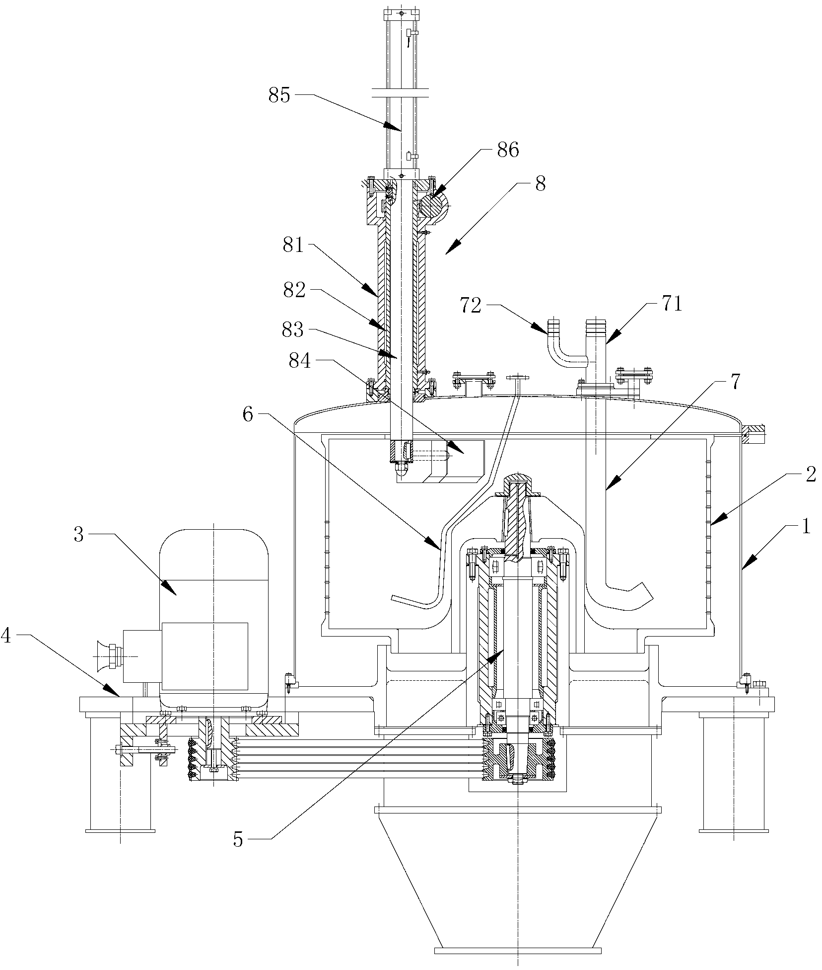
[0021] like figure 1 As shown, a special centrifuge for starch includes a base 4, a housing 1 fixed on the base 4, a main shaft assembly 5 installed on the base 4, a drum 2 arranged on the main shaft assembly 5, and a drum 2 Located in the shell 1, the lower part of the drum 2 is provided with a discharge port, and a drain channel is formed between the outer wall of the drum 2 and the inner side of the shell 1. The main shaft assembly 5 is driven by the motor assembly 3, and the shell 1 is installed There is a scraper 84 assembly 8 for scraping.

[0022] Among them, the frame 4 is different from the three-legged frame 4 currently used. The frame 4 adopts a flat frame 4, and several shells 1 can be fixed on the entire frame 4 at intervals. Each centrifuge shares a machine frame 4. Seat 4, and the driving shaft 83 in the scraper 84 assembly 8 of the centrifuge is controlled by t...


PUM


Abstract

The invention discloses a centrifugal machine special for starch. The centrifugal machine special for the starch comprises a machine base, a shell, a main shaft component and a rotary drum, wherein the shell is fixed on the machine base; the main shaft component is mounted on the machine base; the rotary drum is arranged on the main shaft component; the rotary drum is positioned in the shell; a discharge port is formed in the lower part of the rotary drum; a liquid discharge channel is formed between the outer wall of the rotary drum and the inner side of the shell; the main shaft component is driven by a motor assembly; and a scraper component for scraping is mounted on the shell. The centrifugal machine special for the starch further comprises a feeding pipe and a cleaning pipe, wherein the feeding pipe is fixed at the top of the shell; the lower end of the feeding pipe extends to the bottom of the rotary drum; the cleaning pipe is fixed at the top of the shell; and the lower end of the cleaning pipe extends to the bottom of the rotary drum. The centrifugal machine special for the starch can separate the starch from yellow pulp well, so that the starch is pure white and the separation effect is good.

Description

technical field [0001] The invention relates to a centrifuge, in particular to a special centrifuge for separating starch and yellow pulp. Background technique [0002] The centrifuge uses the strong centrifugal force generated by the high-speed rotation of the drum to accelerate the sedimentation speed of the particles in the liquid and separate the substances with different sedimentation coefficients and buoyant densities in the sample. The current centrifuges generally include a machine base, a shell fixed on the machine base, a spindle assembly installed on the machine base, and a drum arranged on the spindle assembly. The drum is located in the shell, and the bottom of the drum is provided with a discharge The drain channel is formed between the outer wall of the drum and the inner side of the shell. The main shaft assembly is driven by the motor assembly. A scraper assembly for scraping is installed on the shell, and a rotary distributor is installed on the top of the ...

Claims


Application Information

Patent Timeline
Patent Type & Authority Applications(China)
IPC IPC(8): B04B1/00B04B9/02B04B11/08B04B11/02B04B15/06
Inventor 王学明王平
Owner 张家港市轻工设备厂有限公司
Why Eureka
Try Eureka