Spring tool for deburring of bearing holder

A bearing cage and deburring technology, which is applied in the directions of tools, manufacturing tools, and tool holder accessories for lathes, can solve the problems of omission, high deburring cost, low efficiency, etc., and achieve good results.

Active Publication Date: 2013-04-03
DALIAN RUIGU SCI & TECH
View PDF5 Cites 6 Cited by
  • Summary
  • Abstract
  • Description
  • Claims
  • Application Information

AI Technical Summary

Problems solved by technology

The efficiency is very low, and there is a risk of omission. In recent years,

Method used


Image

  • Spring tool for deburring of bearing holder
  • Spring tool for deburring of bearing holder
  • Spring tool for deburring of bearing holder

Examples


Embodiment Construction

[0014] The technical solution of the present invention will be described in detail below in conjunction with the accompanying drawings.

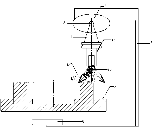
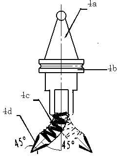
[0015] Spring cutters for deburring bearing cages, e.g. figure 1 As shown, it includes a speed regulating motor 1, a frame 2, a rotating shaft 3, a tool structure 4, a turntable 5 and a speed regulating motor 2 6, and the speed regulating motor 1 is fixedly installed on the upper end of the frame 2, and the speed regulating motor 1 is connected to the rotating shaft 3. The rotating shaft 3 drives the tool structure 4 to rotate, and the rotating direction is clockwise or counterclockwise.

[0016] A turntable 5 is arranged at the lower end of the frame 2, and the bearing cage is fixed on the turntable 5. The rotation of the turntable 5 is controlled by the speed-regulating motor 2 6 at its lower part, and its rotation direction is opposite to that of the rotating shaft 3, which is conducive to improving the deburring efficiency ,Improve prod...


PUM


Abstract

The invention belongs to the field of surface quality processing of a bearing holder, in particular to a spring tool for the deburring of the bearing holder. The spring tool comprises a first speed-adjusting motor, a rack, a rotating shaft, a tool structure, a turntable and a second speed-adjusting motor, wherein the first speed-adjusting motor is fixedly arranged at the upper end of the rack; the first speed-adjusting motor is connected with the rotating shaft; the tool structure is driven to rotate by the rotating shaft; the turntable is arranged at the lower end of the rack; the rotation of the turntable is controlled by the second speed-adjusting motor on the lower part of the turntable; the tool structure comprises a tool shank connected with the rotating shaft; a tool body is fixed on the tool shank; the tool body carries the spring; the blade is connected with the spring; the tool structure is rotated in the same direction along with the rotating shaft; when irregular burs are contacted with the tool disclosed by the invention, the burrs are started to be removed; the sizes and the hardness of the burrs are different; although the situations are not the same, the tool is controlled by the spring and is retractable automatically; the burrs can be removed automatically; the manual deburring is completely replaced; the deburring effect is good; and time and labor are saved.

Description

technical field [0001] The invention belongs to the field of surface quality processing of bearing cages, and in particular relates to a spring cutter used in the deburring process of bearing cages, which is used to solve the problem of complex multi-faceted chamfering and difficult deburring of bearing cages. technical background [0002] The shape of the bearing cage is very complicated, and many equally divided pockets need to be bored out. Such pockets have square, cylindrical, conical and other shapes; and the equal divisions vary from 4 to 200, with odd numbers and even numbers. The size is calculated according to the inner diameter, from 10-2500 mm. All in all, the shape of the bearing cage is an irregular part. The cage is an important part of the bearing, and the quality of the cage determines the quality of the bearing. In particular, the deburring process on the surface of the cage is a key technical problem for domestic bearing companies, and it is also a techn...

Claims


Application Information

Patent Timeline
IPC IPC(8): B23D79/04B23B27/00
Inventor 王世荣马帅石春明唐殿东陶学刚
Owner DALIAN RUIGU SCI & TECH
Why Eureka
Try Eureka