
Cover sealing welding machine of compressor

A welding machine and compressor technology, which is applied in welding equipment, auxiliary welding equipment, welding/cutting auxiliary equipment, etc., can solve the problem of high-precision, high-strength welding technology for compressor covers, and compressor shell compensation. and correction, large size dispersion and other problems, to achieve the effect of light weight, improved quality, and improved stability

Active Publication Date: 2013-04-03
JIANGSU BAIXUE ELECTRIC APPLIANCES
View PDF8 Cites 22 Cited by
  • Summary
  • Abstract
  • Description
  • Claims
  • Application Information

AI Technical Summary

Problems solved by technology

At present, the compressor cover welding machine mainly adopts two trajectory control methods: copy profiling and numerical control theoretical ellipse. In the actual production process, the cover of the compressor shell is deformed and deformed after stamping, stretching and other processing. There is a large deviation from the theoretical value, and the discrete size of the individual is greatly increased. The welding leakage rate is high
[0004] Regardless of profiling or numerical control theoretical elliptical trajectory, neither the deviation between the high discreteness of the individual compressor casing and the fixed theoretical trajectory, nor the deviation between the center of rotation and the theoretical value caused by inaccurate casing positioning cannot be carried out. compensation and correction
Therefore, the conventional welding process and equipment cannot meet the high-precision and high-strength welding technology for the compressor cover

Method used

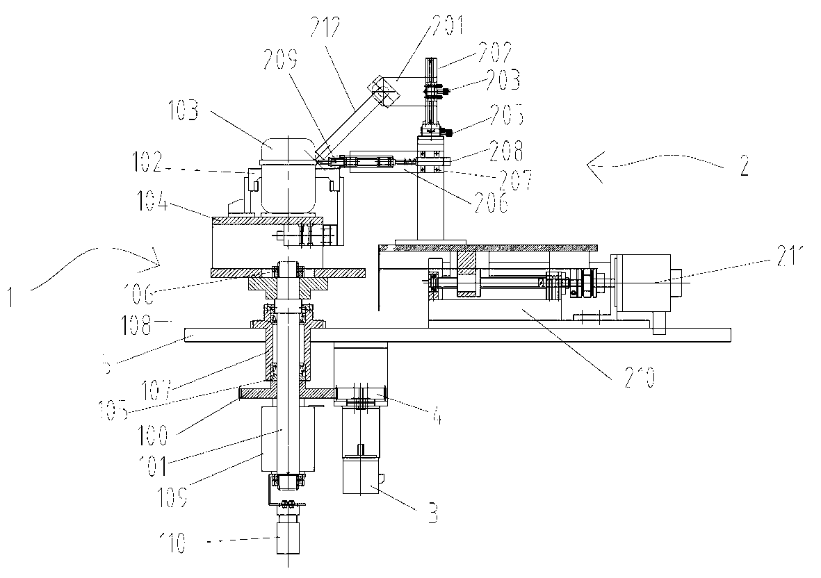
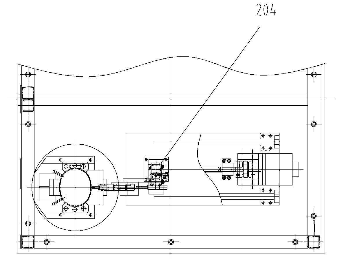
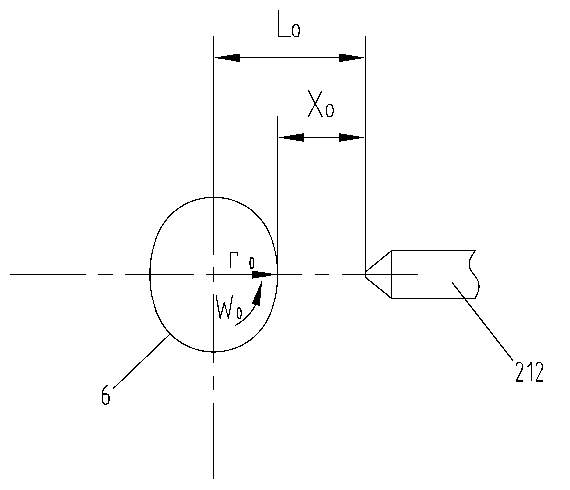

Image

  • Cover sealing welding machine of compressor
  • Cover sealing welding machine of compressor
  • Cover sealing welding machine of compressor

Examples


Embodiment Construction

[0022] Below by specific embodiment the present invention is described in further detail:

[0023] Such as figure 1 The front view of the welding machine shown is mainly composed of a rotary table 1 and a welding part 2. The rotary table 1 is driven to rotate by a rotary servo motor 3. The rotary servo motor 3 is installed at the lower end of the horizontal platform 5, and through gears 4 and The driven gear 100 on the rotary table 1 is connected, and the driven gear 100 is installed on the stepped rotating main shaft 101 through a key (not shown in the figure). There is a shell clamp 102 on the top of the rotary table 1, which is used to tighten the cylinder head 103 of the compressor. The size of the cavity of the housing fixture 102 can be adjusted to meet the requirements of workpieces of different sizes (ie, cylinder heads of compressors). The housing fixture 102 is installed in the cavity of the rotary disc 104, and the rotary disc 104 is connected to the stepped rotar...


PUM


Abstract

The invention relates to a cover sealing welding machine of a compressor. The cover sealing welding machine comprises a welding part and a rotary working table, wherein the welding part comprises a three-dimensional movable sliding table, a welding gun bracket, a translation servo motor, a welding gun head and a control unit; the welding gun bracket is arranged on the three-dimensional movable sliding table; the translation servo motor can be used for driving the welding bracket to slide; the control unit is used for controlling action of the translation servo motor; the rotary working table comprises a shell clamp, a rotary disc, a revolving main shaft and a revolving servo motor; the shell clamp is used for clamping a workpiece; the revolving servo motor is used for driving the revolving main shaft to rotate; the welding part is provided with a detection unit capable of measuring an outer edge parameter of a workpiece shell in real time; the detection unit is in signal connection with the control unit; an outer edge parameter signal of the workpiece shell detected by the detection unit can be timely transmitted to the control unit; and the signal is compared with a parameter pre-stored in the control unit by the control unit to control action of a next step of the translation servo motor. The welding quality is obviously improved by performing real-time measurement and closed-loop control over a cover sealing welding path line of each body.

Description

[0001] technical field [0002] The invention belongs to the field of welding equipment, in particular to a compressor cover welding machine. Background technique [0003] Welding machine is a kind of processing equipment that is often used in the process of processing and production. At present, most welding processes require constant speed, that is, constant linear speed welding. The existing constant speed annular welding machine can meet the requirements of constant speed welding with regular circular curves in the weld seam. However, for non-circular curve welds, using a constant speed, circular seam welding machine cannot ensure that the welding line speed remains constant. The compressor cover has high requirements for welding, that is, the coaxiality of the cover is good, the overall length of the parts requires high precision, and the welding strength between the weldments is also required to be high, that is, the cylinder head and the cylinder bottom of the cover ...

Claims


Application Information

Patent Timeline
IPC IPC(8): B23K37/02B23K37/04B23K37/00
Inventor 钱文军
Owner JIANGSU BAIXUE ELECTRIC APPLIANCES
Learn More