Cam compression clamp

A technology of cams and fixtures, used in clamping, manufacturing tools, supports, etc.

Inactive Publication Date: 2013-04-03
重庆市南川区富民科技推广中心
View PDF0 Cites 5 Cited by
  • Summary
  • Abstract
  • Description
  • Claims
  • Application Information

AI Technical Summary

Problems solved by technology

[0004] The present invention intends to provide a cam pressing fixture to solve the fixing problem of horizontally placed columnar workpieces in the prior art

Method used


Image

  • Cam compression clamp

Examples


Embodiment Construction

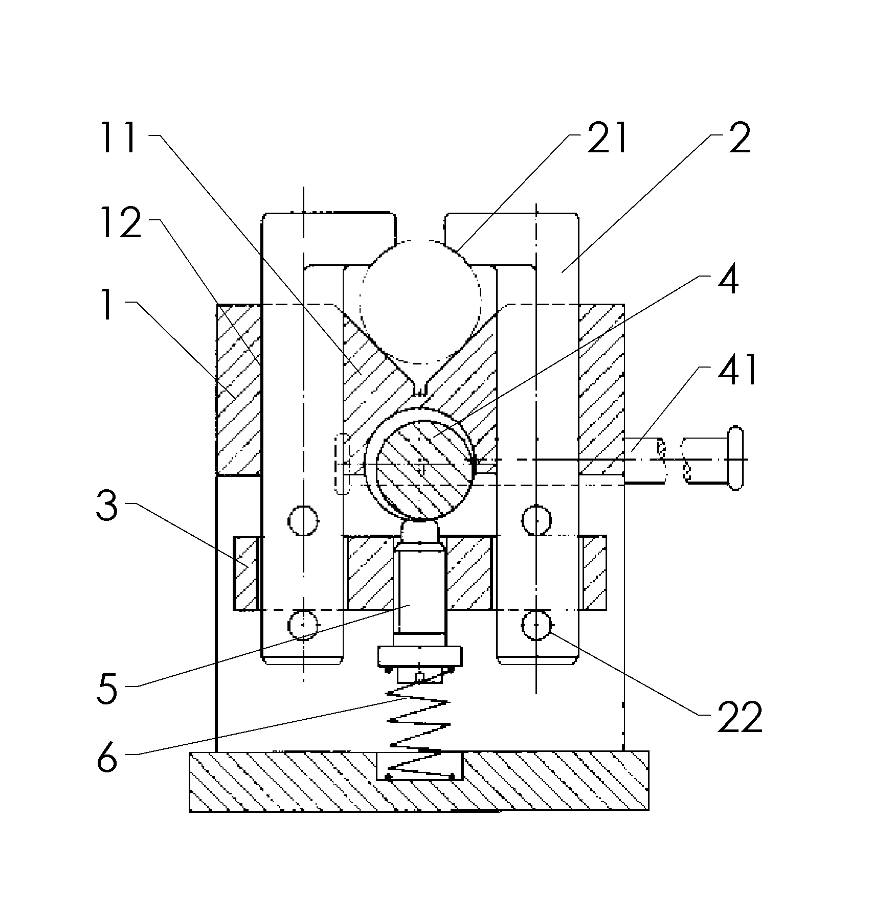
[0010] Such as figure 1 Shown: In this implementation, it includes an organic base 1 and two movable pressing rods 2 on the left and right. The upper surface of the base 1 is a V-shaped support surface 11, and the movable pressing rod 2 slides vertically with the hole 12 provided on the base 1. Socketing, the movable compression rod 2 is provided with the compression surface 21 that cooperates with the circular surface of the workpiece on the top of the V-shaped support surface 11, and the left and right compression surfaces are respectively on the left and right two movable compression rods 2, The left and right movable pressing rods 2 are respectively connected with the connecting plate 3 by bolts.

[0011] The bottom of the V-shaped support surface 11 on the machine base 1 is movably connected with a cam 4, the cam 4 is connected with a handle 41, and the threaded hole on the connecting plate 3 is connected with a positioning rod 5, and the upper end of the positioning rod ...


PUM


Abstract

The invention discloses a cam compression clamp and aims to solve the problem that a horizontally arranged columnar workpiece cannot be well fixed in the prior art. According to the scheme disclosed by the invention, the cam compression clamp is characterized by comprising an engine bed and a clamping jaw, wherein the upper surface of the engine bed is a V-shaped supporting surface; the clamping jaw is connected with the engine bed in the manner of vertical shifting, and a left driven end and a right driven end which are used for compressing the top round face of the workpiece are arranged above the V-shaped supporting surface; the engine bed is hinged with the cam; and a driving end arranged on the clamping jaw is abutted with the lower edge of the cam. The technical scheme has the characteristic that the horizontally-arranged columnar workpiece can be well fixed through matching the engine bed with the clamping jaw.

Description

technical field [0001] The invention relates to a clamp. Background technique [0002] Machine tool fixtures are indispensable and important process equipment in the machinery manufacturing industry, which can ensure the quality of machining, improve production efficiency, reduce production costs, and reduce labor intensity. [0003] In the actual processing process, the shape and structure of the workpiece are ever-changing. It is a long-term task for workers in the mechanical field to design corresponding fixtures for workpieces with different structures. The clamping and fixing of columnar workpieces during processing is one of them. Contents of the invention [0004] The present invention intends to provide a cam pressing fixture to solve the fixing problem of horizontal columnar workpieces in the prior art. [0005] The cam pressing fixture in this program is characterized in that it includes an organic base and jaws, the upper surface of the base is a V-shaped supp...

Claims


Application Information

Patent Timeline
Patent Type & Authority Applications(China)
IPC IPC(8): B23Q3/00
Inventor 袁晴波
Owner 重庆市南川区富民科技推广中心
Why Eureka
Try Eureka