Rotary inner clamping device

An internal clamping and fixture technology, applied in positioning device, clamping, supporting and other directions, can solve the problems of difficult operation, complex device, complex structure, etc., and achieve the effects of low processing and manufacturing cost, simple structure and simple operation.

Inactive Publication Date: 2013-04-03
符雪
View PDF0 Cites 5 Cited by
  • Summary
  • Abstract
  • Description
  • Claims
  • Application Information

AI Technical Summary

Problems solved by technology

[0003] Although all kinds of clamping devices can meet the requirements of workpiece clamping to a certain extent, because they are non-standard devices, they often need to be designed and manufactured according to product mechanism characteristics, production conditions and actu

Method used


Image

  • Rotary inner clamping device

Examples


Embodiment Construction

[0012] Below in conjunction with accompanying drawing and embodiment the technical solution of the present invention is further described:

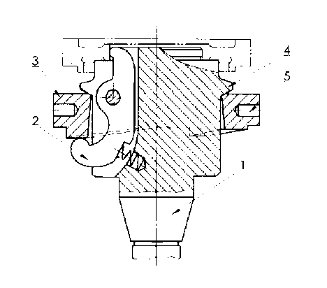
[0013] Such as figure 1 As shown, the present invention provides a rotary internal clamping device, which includes a cylindrical clamp body 1, which is hinged with a circle of evenly distributed claws 2 around the clamp body 1, and the claws 2 rotate radially around the clamp body 1. The driven end is used to clamp the inner hole of the workpiece, and its driving end is against the lower edge of the cam ring 3 sleeved on the fixture main body 1, and the upper edge of the cam ring 3 slides horizontally with a protruding ring 4 provided on the fixture main body 1 Cooperate, the lower edge of the cam ring 3 is provided with a cam against the driving end of the claw 2, the outer edge of the cam ring 3 is provided with a hole 5 for inserting the handle, the claw 2 is provided with three, and the holes 5 for inserting the handle are evenly prov...


PUM


Abstract

The invention relates to a clamping device, in particular to a rotary inner clamping device. The device comprises a cylindrical clamp main body, wherein a ring of uniformly distributed clamping jaws are hinged at the circumference of the clamp main body; the clamping jaws radially rotate along the clamp main body; a driven end of each of the clamping jaws is used for clamping inner holes of a clamping workpiece, and a driving end of the clamping jaw is butted against the lower edge of a cam ring sleeved on the clamp main body; the upper edge of the cam ring is horizontally and slidingly matched with a convex ring arranged on the clamp main body; cams butted against the driving end of the clamping jaw are arranged at the lower edge of the cam ring; and a hole for inserting a handle is formed at the outer edge of the cam ring. By adopting the technical scheme, the rotary inner clamping device is simple in structure, convenient to operate and low in cost.

Description

technical field [0001] The invention relates to a clamping device, in particular to an inner clamping device. Background technique [0002] Generally, during machining, the workpieces to be processed must be fixed, and the clamping device plays a vital role in machining. [0003] Although all kinds of clamping devices can meet the requirements of workpiece clamping to a certain extent, because they are non-standard devices, they often need to be designed and manufactured according to product mechanism characteristics, production conditions and actual needs, and may not be suitable for other clamping devices. Therefore, the development of clamping devices cannot be slack. In addition, many clamping devices now have problems such as complex structure, difficult operation, high requirements for operators, complex devices, and high cost. Contents of the invention [0004] The technical problem to be solved by the present invention is to provide a clamping device with simple s...

Claims


Application Information

Patent Timeline
IPC IPC(8): B23Q3/00
Inventor 符雪
Owner 符雪
Why Eureka
Try Eureka