Stern rotary drum

The technology of a stern drum and a cylinder body is applied in the field of a stern drum of an offshore engineering ship, and achieves the effect of reducing installation accuracy requirements and convenient installation.

Inactive Publication Date: 2013-04-03
GUANGXIN SHIPBUILDING & HEAVY IND
View PDF4 Cites 9 Cited by
  • Summary
  • Abstract
  • Description
  • Claims
  • Application Information

AI Technical Summary

Problems solved by technology

However, because it is connected with the hull structure by flanges, the two ends of the shaft of the stern drum are respectively restrained by a set of bolts, which also puts forward very high requirements for the accuracy of the manufacture and installation of the hull structure.

Method used


Image

  • Stern rotary drum
  • Stern rotary drum
  • Stern rotary drum

Examples


Embodiment Construction

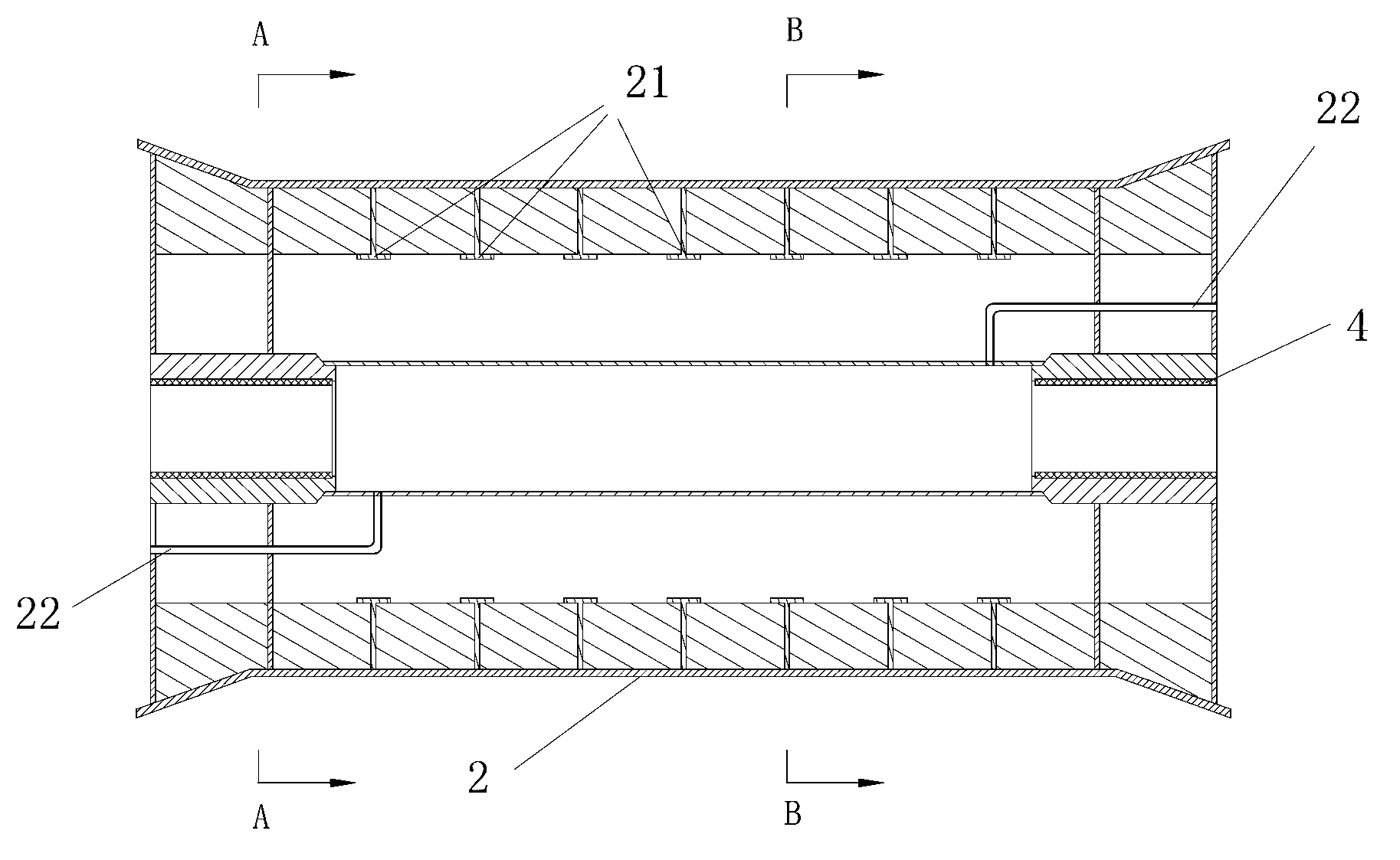
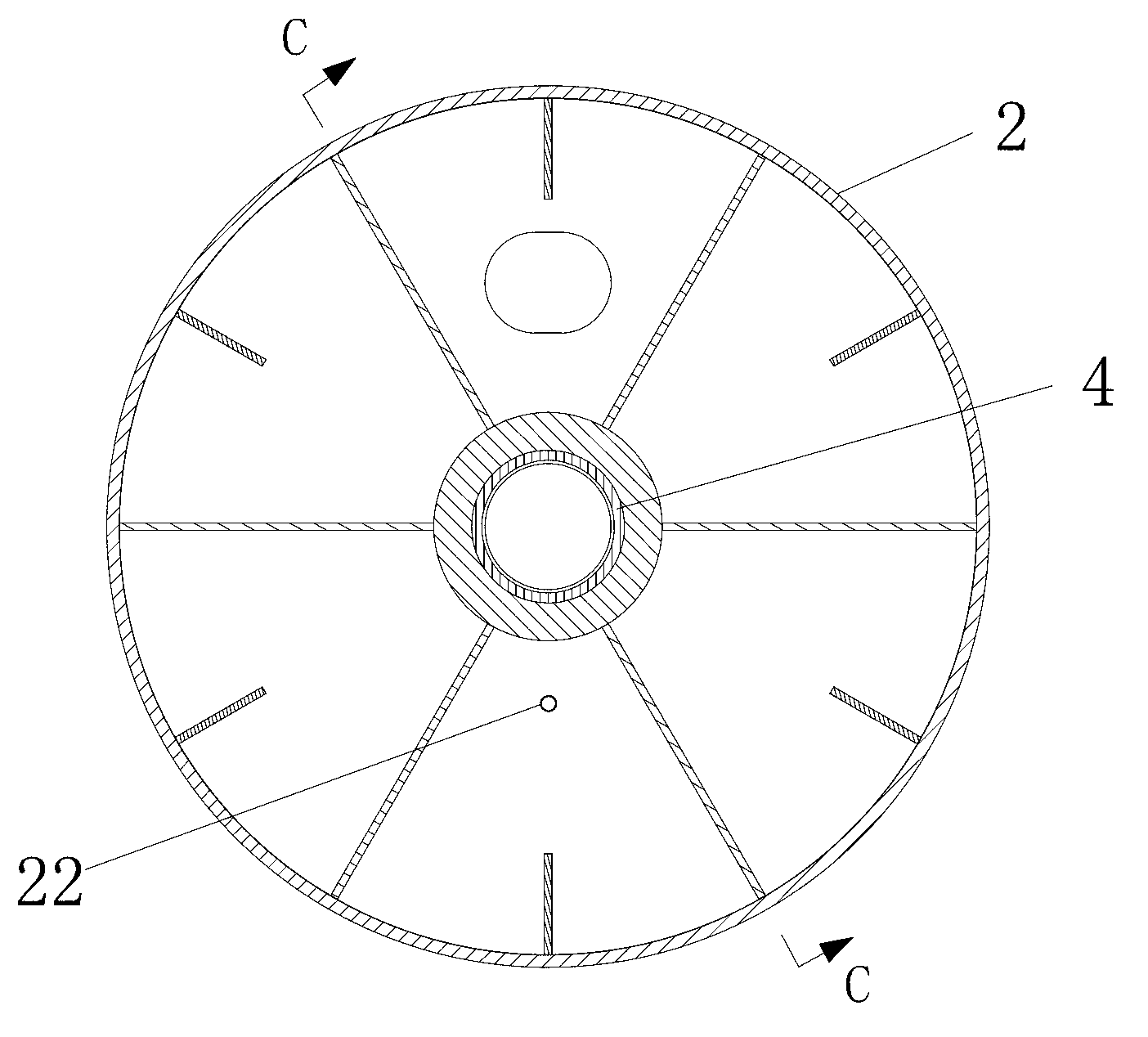
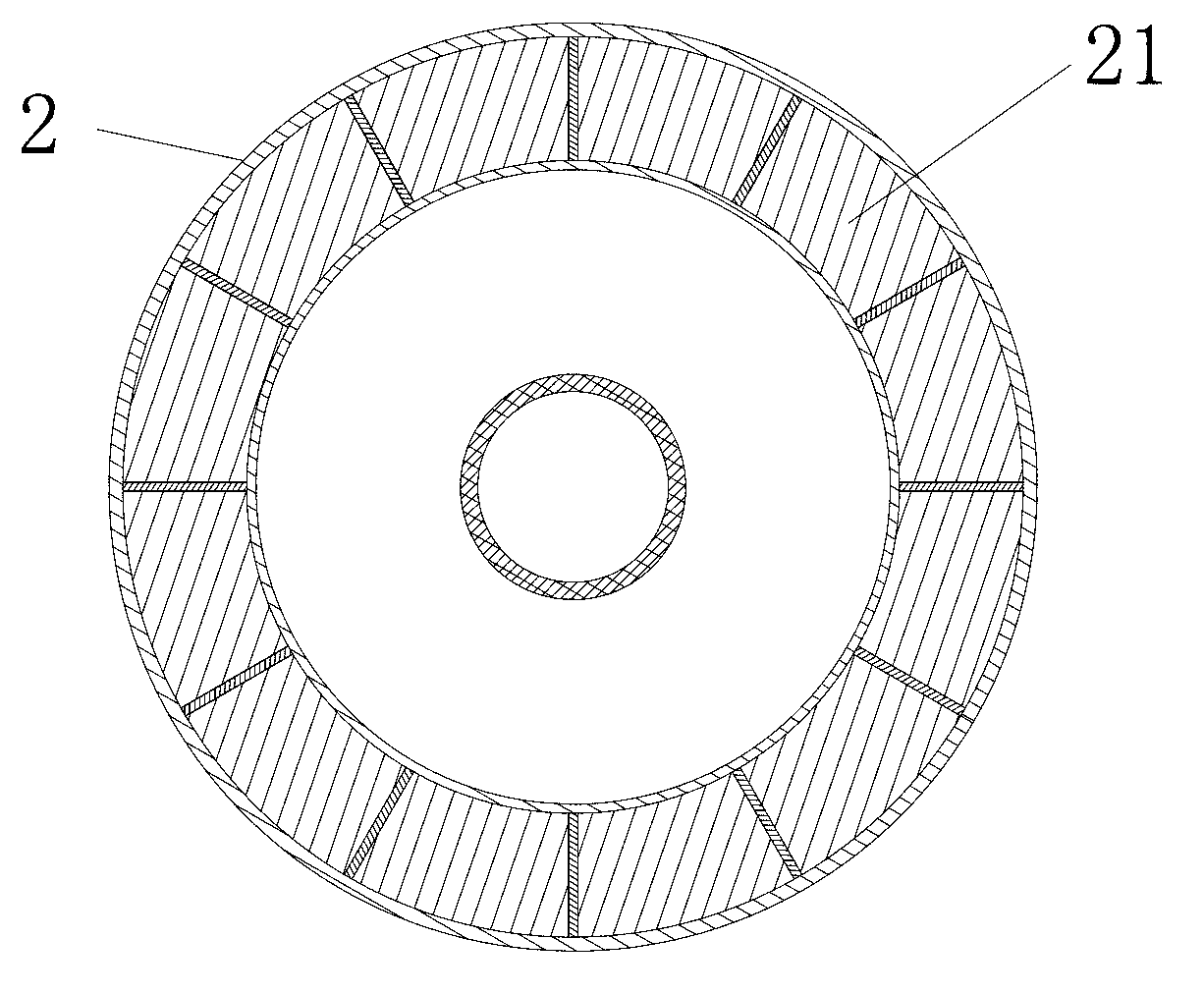
[0027] A stern drum, which includes a shaft body 1 and a cylinder body 2 arranged on the shaft body through a bearing 4, a plurality of transverse annular ribs 21 arranged along the circumferential direction of the shaft body 1 are arranged in the cylinder body 2, and radially The four longitudinal stiffeners arranged in directions of 30°, 60°, 210°, and 240°, the transverse annular rib 21 and the longitudinal annular rib improve the load capacity of the cylinder 2 and reduce the weight of the cylinder 2 at the same time.

[0028] It also includes a shaft fork 3, the shaft fork 3 is welded and fixed on the hull, the shaft fork 3 includes a clamping portion 31, the shaft body 1 forms a matching portion 11 corresponding to the clamping portion of the shaft fork 3, and the coupling portion 11 is fixed in the clamping part 31 , so that the shaft fork 3 can support and fix the shaft body 1 , and an isolation spacer 6 and epoxy resin 5 are also arranged between the shaft fork 3 and t...


PUM


Abstract

The invention relates to a stern rotary drum of ships, and in particular to a stern rotary drum, which comprises a shaft body and a drum body arranged on the shaft body through a bearing, wherein the drum body is internally provided with a plurality of horizontal ring-shaped rib plates arranged along the periphery of the shaft body. The stern rotary drum is characterized by also comprising a shaft fork, wherein the shaft body is fixed on the shaft fork. The stern rotary drum is simple in structure, convenient to install, strong in loading capacity and flexible in operation.

Description

Technical field: [0001] The invention relates to a stern device of a ship, in particular to a stern drum applied to an ocean engineering ship. Background technique: [0002] As an important part of marine engineering, marine workboats are responsible for the transportation of manpower and materials and the towing of marine structures for marine engineering. When the marine workboat is towing the marine structure, it is generally driven by the towing winch located in the ship. The wear of the hull, on the other hand, when the cable or anchor chain moves on the stern drum, the stern drum rotates accordingly, similar to a fixed pulley, which can greatly reduce sliding friction and reduce severe wear on the cable or anchor chain due to friction. [0003] The early stern drum used a single-shell drum with a simple structure. It was welded by plates to form a closed cylindrical cavity, and a ring-shaped stiffener was arranged inside. It was defined as a "radial reinforced" stern...

Claims


Application Information

Patent Timeline
Patent Type & Authority Applications(China)
IPC IPC(8): B63B21/22B63B21/50
Inventor 陈朝俊林从飞易永光周启智罗元方
Owner GUANGXIN SHIPBUILDING & HEAVY IND
Why Eureka
Try Eureka