Yarn winding machine and yarn winding unit

A winding machine and yarn technology, applied in the field of yarn splicing devices, can solve problems such as thread breakage, and achieve the effect of improving the freedom of layout

Active Publication Date: 2013-04-03
MURATA MASCH LTD
View PDF9 Cites 9 Cited by
  • Summary
  • Abstract
  • Description
  • Claims
  • Application Information

AI Technical Summary

Problems solved by technology

If yarn slack occurs when winding starts again, the slack yarn will be caught on the traverse guide and cause thread breakage

Method used


Image

  • Yarn winding machine and yarn winding unit
  • Yarn winding machine and yarn winding unit
  • Yarn winding machine and yarn winding unit

Examples


Embodiment Construction

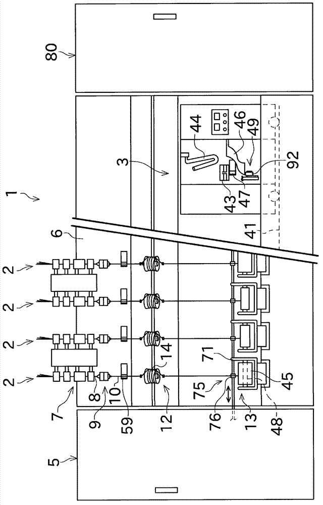
[0042] Next, a spinning machine as a yarn winding machine according to an embodiment of the present invention will be described with reference to the drawings. figure 1 The illustrated spinning machine (spinning machine) 1 has a plurality of spinning units (yarn winding units) 2 arranged side by side, a yarn splicing cart 3, a fan box 80, and a motor box 5.

[0043] A negative pressure source (not shown) and the like for supplying negative pressure to each spinning unit 2 are arranged in the fan box 80. A driving source common to each spinning unit 2 is arranged in the motor housing 5.

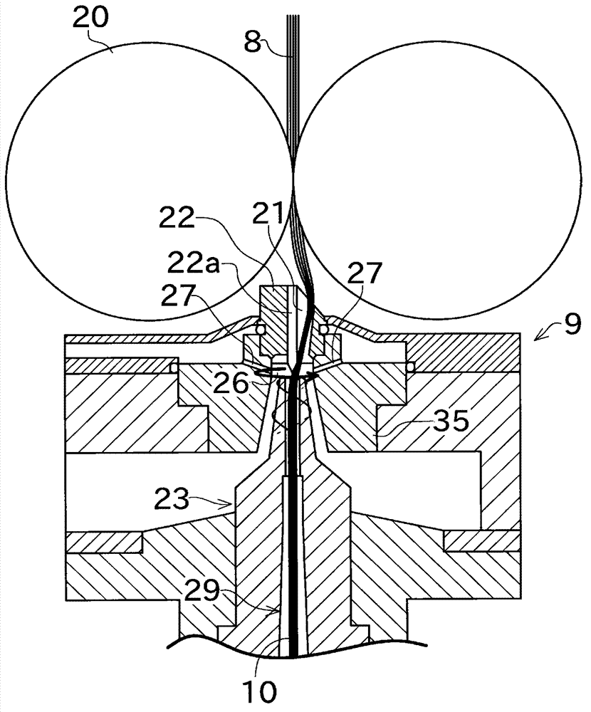
[0044] Such as figure 2 As shown, each spinning unit 2 has as a main structure: a drafting device 7, a spinning device (yarn feeding section) 9, a yarn accumulating device 12, and a winding device (winding section) arranged in order from upstream to downstream. ) 13. Each spinning unit 2 spins the fiber bundle 8 sent from the drafting device 7 by the spinning device 9 to produce the spun yarn 10,...


PUM


Abstract

The invention provides a yarn winding machine and a yarn winding unit. The yarn winding machine includes a winding device (13) adapted to wind a yarn into a package (45); a spinning device (9) adapted to supply a spun yarn (10) to the winding device (13); a yarn joining device (43) adapted to perform a yarn joining operation to join the spun yarn between the package (45) and the spinning device (9); and a moving means (30). The moving means (30) can move the yarn joining device (43) between a yarn joining position and a retreated position, the yarn joining position being a position located close to a yarn path between the package (45) and the spinning device (9) during a normal winding, and the retreated position being a position located away from the yarn path.

Description

Technical field [0001] The present invention relates to a yarn joining device of a yarn winding machine. Background technique [0002] Known is a yarn winding machine that winds the yarn on a bobbin to form a package. Such a yarn winding machine includes, for example, a spinning machine disclosed in JP 2010-77576 A (Patent Document 1). As described in Patent Document 1, the spinning machine has: a spinning device that twists a fiber bundle to produce a spun yarn; and a spinning device that winds the spun yarn produced by the spinning device on a bobbin to form a package Winding device. [0003] The spinning machine of Patent Document 1 has a yarn splicing cart, which connects the yarn on the spinning device side and the yarn on the package side when the spun yarn between the spinning device and the package is in a disconnected state (Connecting yarn). The yarn joining cart has a yarn joining device for connecting the yarn on the spinning device side and the yarn on the package ...

Claims


Application Information

Patent Timeline
Patent Type & Authority Applications(China)
IPC IPC(8): B65H54/22B65H69/06
CPCB65H69/04B65H2701/31B65H69/061B65H54/26
Inventor 上田健一丰田贵大
Owner MURATA MASCH LTD
Why Eureka
Try Eureka