
Multiple-chamber type double steel plate concrete combined shear wall

A combined shear wall and concrete technology, applied in the direction of walls, building components, earthquake resistance, etc., can solve the problems of loss of bearing capacity, excessive rigidity, and large temperature stress of the structure, so as to enhance the seismic performance, and facilitate the adjustment and reduction of stiffness. The effect of temperature stress

Inactive Publication Date: 2013-04-03
BEIHANG UNIV
View PDF8 Cites 7 Cited by
  • Summary
  • Abstract
  • Description
  • Claims
  • Application Information

AI Technical Summary

Problems solved by technology

[0011] Therefore, it can be said that the double-steel plate concrete composite shear wall is a very ideal lateral force-resisting member, but in practical applications, it still has the disadvantages of excessive rigidity and unsatisfactory ductility
Excessive rigidity is not convenient for the distribution and adjustment of structural rigidity, resulting in the excessive concentration of the entire structural rigidity in the double-steel plate concrete composite shear wall, which is not convenient for the realization of multiple anti-seismic defense lines and overall load-carrying advocated in the code
The ductility is not very ideal, which is not conducive to the self-seismic resistance of the double steel plate concrete composite shear wall
In addition, excessive stiffness will cause the temperature stress of the structure to be particularly large, causing it to lose part of its bearing capacity.

Method used


Image

  • Multiple-chamber type double steel plate concrete combined shear wall
  • Multiple-chamber type double steel plate concrete combined shear wall
  • Multiple-chamber type double steel plate concrete combined shear wall

Examples


Embodiment Construction

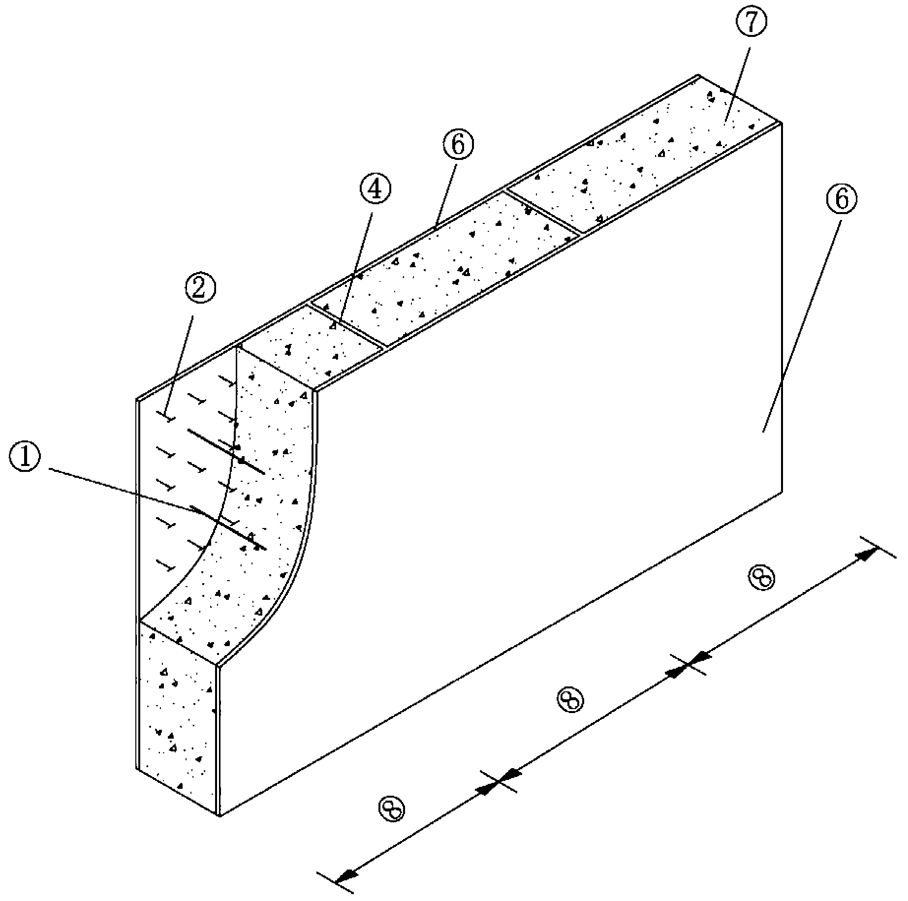
[0030] figure 1 It is the axonometric drawing of the traditional double steel plate concrete composite shear wall.

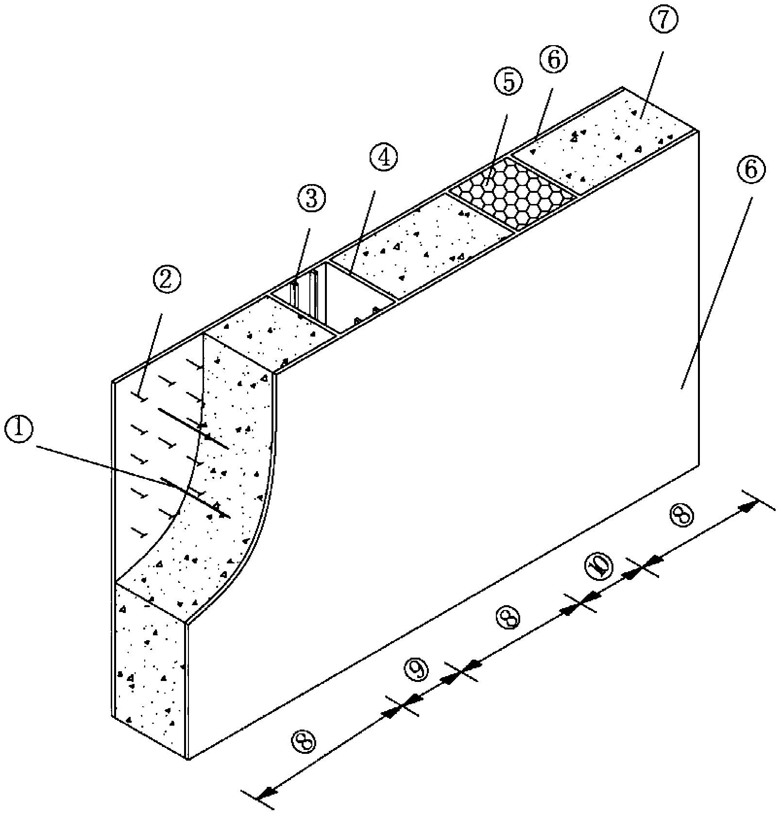
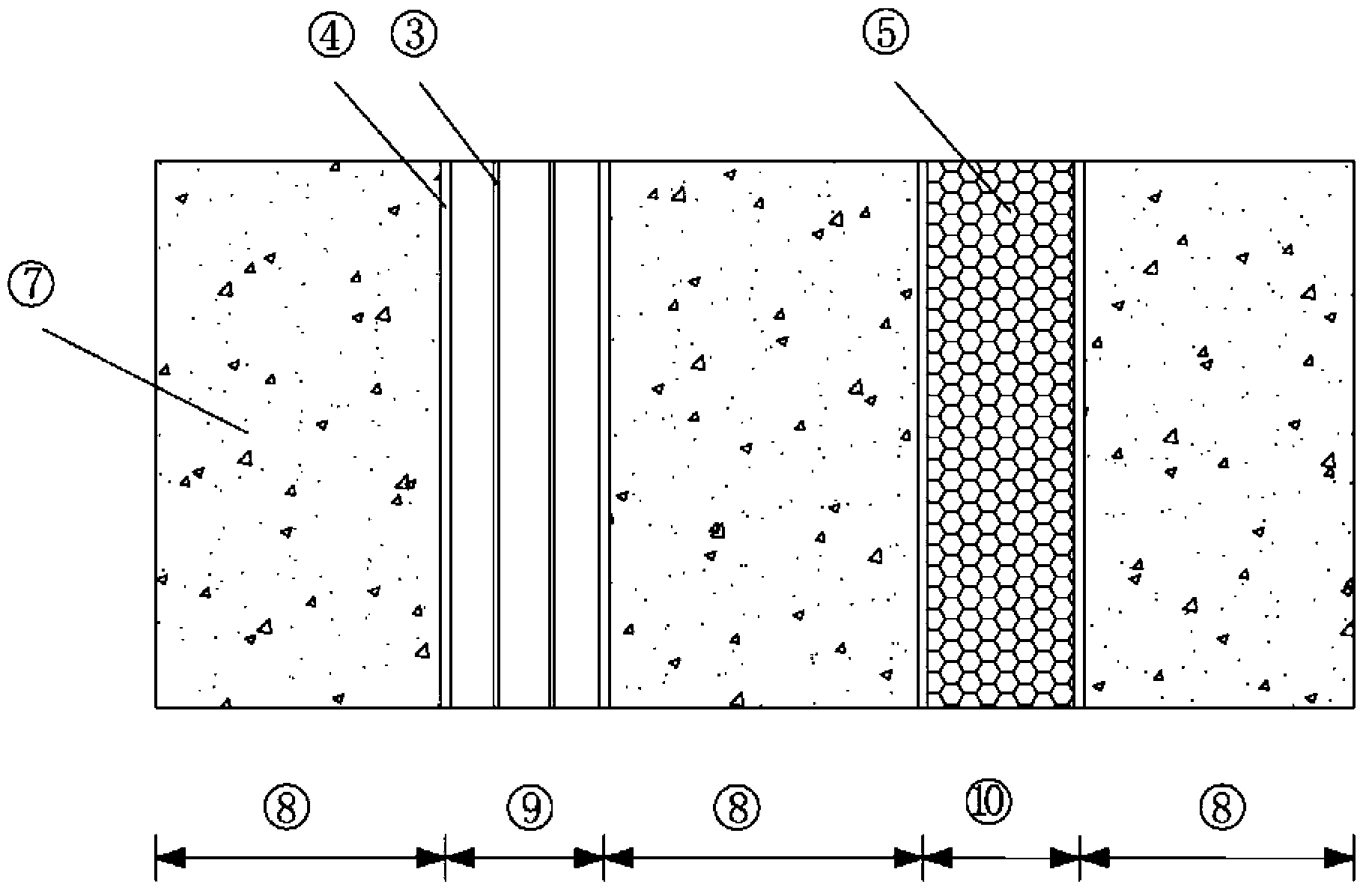
[0031] See figure 2 , image 3 , the present invention is a multi-chamber double steel plate concrete composite shear wall, which is composed of two steel plates 6 on the surface of the wall and plain concrete 7 inside the wall, between which there are studs 2 welded on the steel plates, The tension bars 1 and the vertical partitions 4 are connected to ensure the cooperative work between the two. And use the vertical partition 4 to divide the wall space between the two steel plates into compartments, and then pour concrete in a part of the compartments to form a concrete compartment 8, and the other part of the compartments is kept empty and filled with porous energy-consuming materials such as aluminum foam. The material 5 forms empty chambers 9 and energy-dissipating material-filled chambers 10 , thereby forming alternate distributions of concrete chambers...


PUM


Abstract

The invention relates to a multiple-chamber type double steel plate concrete combined shear wall, which integrally consists of two wall body surface steel plates (6) and a wall inner plain concrete (7), wherein the wall body surface steel plates (6) and the wall inner neat concrete (7) are connected by bolt screws (2), split reinforced bars (1) and vertical separating plates (4) to ensure the cooperated work, the bolt screws (2), the split reinforced bars (1) and the vertical separating plates (4) are welded on the steel plates, the wall body space between the two steel plates is separated into bin chambers by the vertical separating plates (4), the inside of one part of bin chambers is cast with concrete to form concrete bin chambers (8), the other part of bin chambers is kept empty and is filled with a foam aluminum porous energy dissipating material to form an empty bin chamber (9) and an energy dissipating material filling bin chamber (10), and then the alternative distribution of the concrete bin chambers (8), the empty bin chamber (9) and the energy dissipating material filling bin chamber (10) is realized. The multiple-chamber type double steel plate concrete combined shear wall has the advantage that the rigidity is reduced, and the extensibility is increased, so the suitability is further improved.

Description

Technical field: [0001] The invention relates to a novel shear wall, in particular to a multi-chamber double steel plate concrete composite shear wall, which belongs to the technical field of civil engineering structures. Background technique [0002] In recent years, with the rapid development of my country's economy, urbanization has been greatly accelerated. The influx of a large number of people into the city and the development of the economy have made land resources increasingly tense. In order to alleviate the contradiction between man and land, residential and commercial buildings are showing a trend of high-rise and super high-rise development, which also puts forward higher requirements for the corresponding structural form. First, it is required to have good mechanical properties, such as anti-corrosion Side shift stiffness, ultimate bearing capacity, etc.; second, it is required to have good ductility and energy dissipation capacity, so that the whole building c...

Claims


Application Information

Patent Timeline
IPC IPC(8): E04B2/68E04B1/98
Inventor 郭全全黄泽宇赵唯以谭力
Owner BEIHANG UNIV
Learn More