Cooling fan for engine, cooling system for engine and engineering machinery

A technology for engine cooling and engineering machinery, which is applied in the direction of engine cooling, engine components, machine/engine, etc. It can solve the difficulties in matching design and practical application of cooling systems, weaken the exhaust capacity of cooling fans, and reduce the heat dissipation capacity of the cooling system of the whole machine and other problems, to achieve the effect of small space occupation, simple structure, and avoiding the dead angle of supplementary air

Inactive Publication Date: 2013-04-03
SANY HEAVY IND CO LTD (CN)
View PDF5 Cites 0 Cited by
  • Summary
  • Abstract
  • Description
  • Claims
  • Application Information

AI Technical Summary

Problems solved by technology

The exhaust speed of the cooling fan gradually decreases from the head of the fan blade 1' to the centerline of the hub 3', and a low wind speed area is formed near the center of the hub 3', which weakens the exhaust capacity of the cooling fan, thereby reducing The heat dissipation capacity of the cooling system of the whole machine brings great difficulties to the matching design and practical application of the cooling system

Method used


Image

  • Cooling fan for engine, cooling system for engine and engineering machinery
  • Cooling fan for engine, cooling system for engine and engineering machinery
  • Cooling fan for engine, cooling system for engine and engineering machinery

Examples


Embodiment Construction

[0025] It should be noted that, in the case of no conflict, the embodiments of the present invention and the features in the embodiments can be combined with each other.
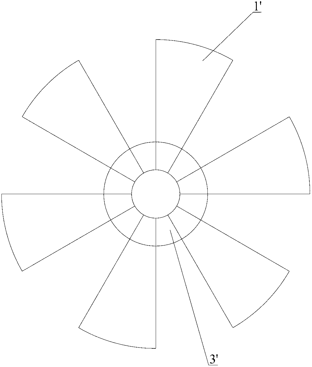
[0026] The basic idea of ​​the present invention is to increase the exhaust air volume in the low wind area of ​​the cooling fan by adding small fan blades along the axial direction of the hub, thereby optimizing the air exhaust performance of the cooling fan.

[0027] The preferred embodiments of the present invention will be further described below in conjunction with the accompanying drawings. It should be noted that the tail end of the present invention refers to the end of the two ends of the component that is close to the hub. Correspondingly, the tail refers to the end of the component that is close to the hub. The head end refers to the end opposite to the tail end.

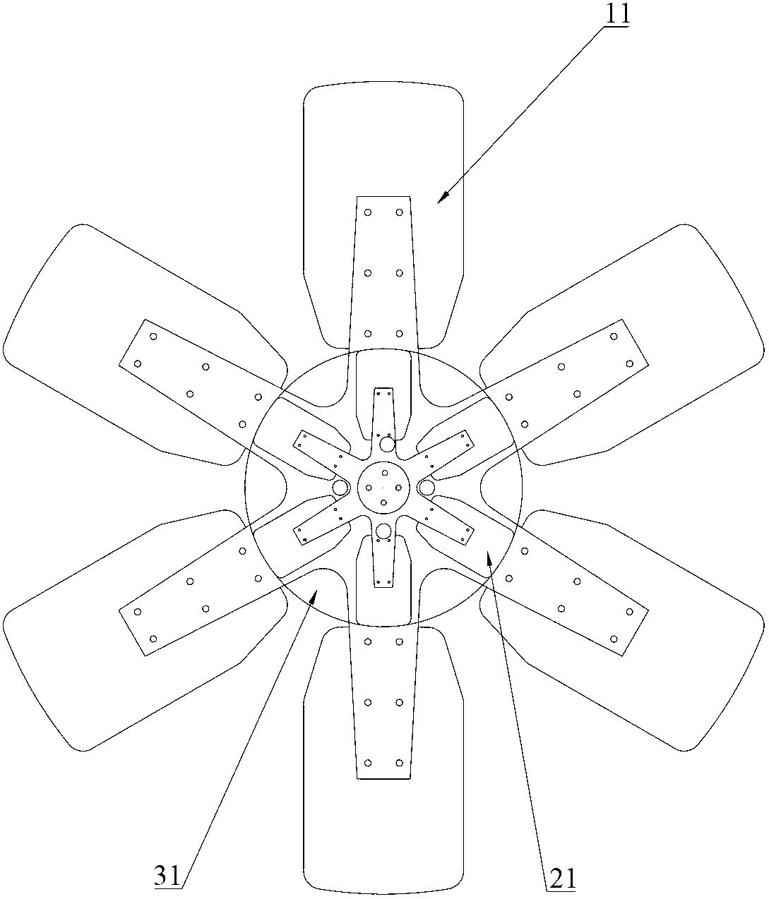
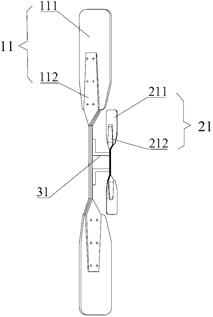
[0028] figure 2 and image 3 The structure of the engine cooling fan provided by Embodiment 1 of the present invention is shown, an...


PUM


Abstract

The invention discloses a cooling fan for an engine, a cooling system for the engine and engineering machinery. The cooling fan for the engine comprises a hub, a first fan blade component and a second fan blade component, wherein the first fan blade component comprises a plurality of first fan blades; the first fan blades are mounted on the hub and extend in a radial form along the radial direction of the hub; the second fan blade component comprises a plurality of second fan blades; the second fan blades are mounted on the hub and extend in the radial form along the radial direction of the hub; and distances from head ends of the first fan blades to the axis of the hub are more than the distances from the head ends of the second fan blades to the axis of the hub. The cooling fan for the engine provided by the invention has the advantages of complete air exhausting area coverage, strong air exhausting capacity, simple structure and small occupied space.

Description

technical field [0001] The invention relates to the field of construction machinery, in particular to an engine cooling fan, an engine cooling system and construction machinery. Background technique [0002] The engine will generate a lot of heat during operation, making the engine temperature too high. The engine needs to be moderately cooled during rotation so that it can be kept at a suitable temperature to meet the requirements of good engine performance, durability and exhaust emissions. The engine cooling system plays a key role here. [0003] At present, the most commonly used engine cooling system is liquid cooling, that is, the liquid used for cooling passes through the circulation system, and then dissipates heat through the radiator to cool down the engine. Cooling needs. The performance of the cooling fan has an important influence on the cooling effect of the engine. [0004] Construction machinery often has to work in an environment with high temperature, h...

Claims


Application Information

Patent Timeline
Patent Type & Authority Applications(China)
IPC IPC(8): F01P5/02F04D29/32
Inventor 周永鑫吴双斌陈卫平
Owner SANY HEAVY IND CO LTD (CN)
Why Eureka
Try Eureka