Fuel heating in combined cycle turbomachinery

A turbomachinery, combined cycle technology, applied in the fuel heating of turbine/propulsion devices, turbine/propulsion fuel delivery systems, mechanical equipment, etc., can solve problems such as increasing the cost of fuel gas heating

Inactive Publication Date: 2013-04-03
GENERAL ELECTRIC CO
View PDF5 Cites 13 Cited by
  • Summary
  • Abstract
  • Description
  • Claims
  • Application Information

AI Technical Summary

Problems solved by technology

However, the use of high pressure water significantly increases the cost of fuel gas heating while having reliability issues in case of failure

Method used


Image

  • Fuel heating in combined cycle turbomachinery
  • Fuel heating in combined cycle turbomachinery
  • Fuel heating in combined cycle turbomachinery

Examples


Embodiment Construction

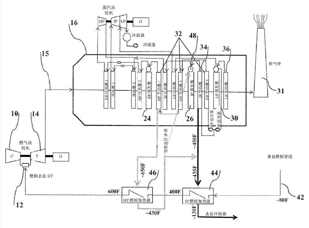
[0024] figure 2 A schematic flow diagram of a three-pressure combined cycle turbomachine is shown. The machine comprises a compressor 10 , a combustor 12 and a turbine 14 powered by expansion of the hot gases produced in the combustor 12 for driving a generator G . Exhaust gas from the gas turbine 14 is supplied via line 15 to a heat recovery steam generator (HRSG) 16 for recovering waste heat from the exhaust gas. The HRSG includes high pressure (HP), intermediate pressure (IP) and low pressure (LP) sections. Each of the HP, IP, LP sections includes a respective evaporator section 24, 26, 30, and a respective economizer section 32, 34, 36 within the respective evaporator section Used to preheat water before converting it to steam. Water is fed to HRSG 16 to generate steam. Heat recovered from the exhaust gas supplied to the HRSG 16 is transferred to water / steam in the HRSG 16 for generating steam which is supplied to a steam turbine ST for driving an electric generator. ...


PUM


Abstract

The invention discloses a method for improving efficiency of a combined cycle turbomachinery. Combined cycle efficiency can be improved by heating fuel in a gas turbine fuel line in two stages using (i) hot water from an HP economizer of a heat recovery steam generator (HRSG) in a second stage and (ii) hot water from an IP economizer of the HRSG and water output flow from the second stage in a first stage. Efficiency may be further improved by adding one or more fuel preheaters using hot water from the IP feedpump and sequential injections of hot water into the fuel.

Description

technical field [0001] The present invention relates to combined cycle turbomachinery and, more particularly, to improving combined cycle efficiency by heating fuel in fuel lines entering gas turbines in stages. Background technique [0002] Combined cycle turbomachines utilize a gas turbine (GT) as a prime mover to generate power. These GT engines operate on the principle of Brayton cycle thermodynamics and typically have high exhaust gas flow and relatively high exhaust gas temperature. When directed into a heat recovery boiler, typically called a heat recovery steam generator (HRSG), these exhaust gases produce steam that can be used to generate more power. The generated steam can be directed to a steam turbine (ST) to generate additional power. In this way, the GT performs work via the Brayton cycle, and the ST generates power via the Rankine cycle. Hence the name "combined cycle". [0003] Fuel gas is typically heated in combined cycle turbomachines to increase ther...

Claims


Application Information

Patent Timeline
Patent Type & Authority Applications(China)
IPC IPC(8): F02C7/224
CPCF02C6/04F02C6/003F02C6/18F02C7/224
Inventor J.E.肖勒斯D.F.比迪伊K.芒德拉
Owner GENERAL ELECTRIC CO
Why Eureka
Try Eureka