Antistatic structure of fuel pipe

a technology of antistatic structure and fuel pipe, which is applied in the direction of machines/engines, machine supports, applications, etc., can solve the problems of increasing the number of parts, and achieve the effect of simple structur

Inactive Publication Date: 2005-07-12
HONDA MOTOR CO LTD
View PDF26 Cites 29 Cited by
  • Summary
  • Abstract
  • Description
  • Claims
  • Application Information

AI Technical Summary

Benefits of technology

[0007]In consideration of the circumstances, it is an object of the invention to remove electric charges from a fuel pipe charged in contact with a fuel by using a simple structure.
[0009]According to the structure described above, the fuel pipe and the pipe are coupled to each other through the conductive clamp in at least one portion. Therefore, it is possible to transfer the electric charges of the fuel pipe charged in contact with a fuel to the body through the conductive clamp and the pipe. Consequently, it is possible to suppress the generation of a great discharge, thereby preventing a deterioration in the fuel pipe. Moreover, the pipe is originally connected electrically to the body. Therefore, a special member for electrically connecting the conductive clamp to the body is not required so that the number of parts and cost can be reduced.
[0011]According to the structure described above, the portions in which the fuel pipe and the pipe are provided close to each other in parallel are connected through the conductive clamp. Therefore, the conductive clamp can have a small and simple structure.
[0013]According to the structure described above, the brake pipe is electrically connected to the vehicle body through a bracket for supporting a connecting portion to a brake hose. Therefore, a special member for electrically connecting the brake pipe to the body is not required so that the number of parts and cost can be reduced.
[0015]According to the structure described above, the conductive clamp is constituted by a synthetic resin including carbon black. Therefore, it is possible to cause the conductive clamp to have a flexibility to easily clamp the fuel pipe and the pipe, and furthermore, to reliably carry out electrical conduction between the fuel pipe and the pipe.

Problems solved by technology

However, there has conventionally been a problem in that a special member such as the bracket or the bolt is required for fixing the piping holding portion formed of the conductive resin to the vehicle body in the state of electrical connection, resulting in an increase in the number of parts.

Method used


Image

  • Antistatic structure of fuel pipe
  • Antistatic structure of fuel pipe
  • Antistatic structure of fuel pipe

Examples


Embodiment Construction

[0021]An embodiment of the invention will be described below based on an embodiment of the invention shown with reference FIGS. 1 to 4.

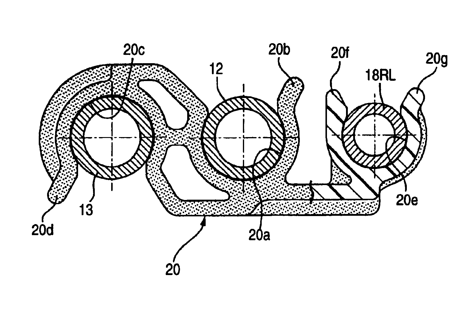
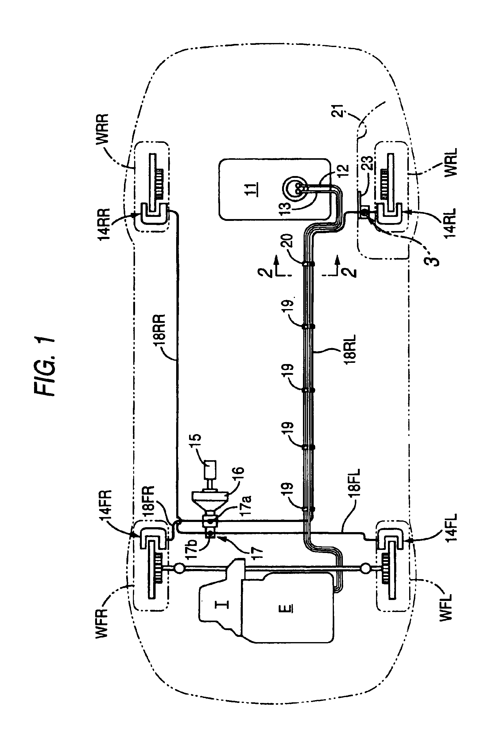
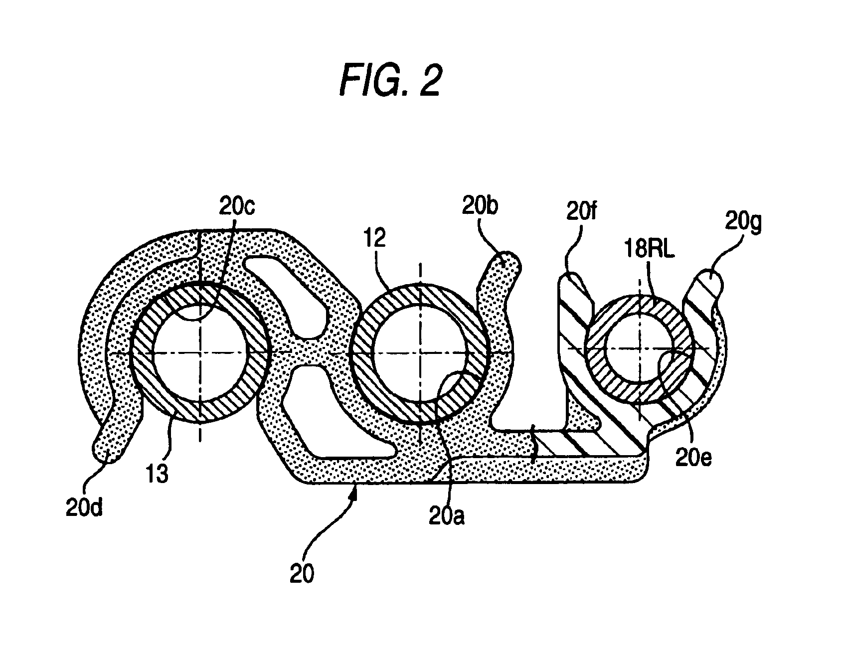
[0022]As shown in FIG. 1, a fuel tank 11 is mounted on a rear part of a vehicle body of a vehicle, and the fuel tank 11 and an engine E mounted on the front part of the body are connected to each other through a feed pipe 12 and a return pipe 13. The feed pipe 12 for feeding a fuel to the engine E has an upstream end connected to a strainer and a fuel pump which are provided in the fuel tank 11 and are not shown, and a downstream end connected to an injector which is provided in the engine E and is not shown. The return pipe 13 for returning an excess fuel from the engine E to the fuel tank 11 has an upstream end connected to the injector and a downstream end connected to the upper space of the fuel tank 11.

[0023]Brake calipers 14FL, 14FR, 14RL and 14RR are provided on left and right front wheels WFL and WFR to be driving wheels connected to the engi...


PUM


Abstract

In an antistatic structure of a fuel pipe, the fuel pipe to be charged in contact with a fuel, and a brake pipe connected electrically to a vehicle body are coupled to each other through a conductive clamp in at least one portion.

Description

BACKGROUND OF THE INVENTION[0001]1. Field of the Invention[0002]The present invention relates to an antistatic structure for preventing a fuel pipe from being charged in contact with a fuel that has been charged by friction with a fuel pipe or a strainer.[0003]2. Description of the Related Art[0004]A fuel tank for an automobile is provided with a strainer for removing foreign matters in a fuel and various pipes such as a feed pipe, a return pipe, and a vent pipe. The feed pipe feeds a fuel to an injector of an engine. The return pipe returns, to a fuel tank, an excess fuel which is not jetted from the injector in the engine. The vent pipe is connected to a filler tube at an upper space of the fuel tank so as not to prevent the injection of the fuel from the filler tube to the fuel tank. If the fuel is charged by friction when flowing in the pipes or the strainer, the pipes are charged in contact with the fuel. If the pipes are thus charged, a difference in potential might be made be...

Claims


Application Information

Patent Timeline
Patent Type & Authority Patents(United States)
IPC IPC(8): B60R16/06F16L3/22F16L5/02F16L3/08F16L3/223B60K15/01F02M37/00
CPCB60R16/06F16L3/08F16L3/223F16L5/027
Inventor SUGIYAMA, MITSUOHASEGAWA, YASUHIROOGAWA, TORUNOBATA, HIDEKAZU
Owner HONDA MOTOR CO LTD
Why Eureka
Try Eureka