Systems and methods for thermal management in a gas turbine powerplant

a technology of thermal management and gas turbine power, which is applied in the direction of machines/engines, turbine/propulsion fuel heating, instruments, etc., can solve the problems of varnish or coke deposits that can foul the combustor fuel nozzle, oil jet, and other fuel, control, lubrication, and the temperature of engine fuel to exceed the operational limit, so as to reduce the effect of engine fuel temperature, increasing the temperature limit of fuel, and reducing coke deposition

Inactive Publication Date: 2011-07-26
PROPULSION GAS TURBINE & ENERGY EVALUATIONS
View PDF39 Cites 29 Cited by
  • Summary
  • Abstract
  • Description
  • Claims
  • Application Information

AI Technical Summary

Benefits of technology

[0020]It is an object of the present invention to provide better management of the heat generated by a gas turbine powerplant and carried by its fuel, lubricating fluids, and hydraulic fluids, and more particularly for providing improved heat management in a gas turbine aircraft engine.

Problems solved by technology

One of the drawbacks of this type of engine thermal management is that the heat added to the fuel by the aircraft and / or engine can cause the engine fuel temperature to exceed operational limits.
In some cases, it could even fail to provide adequate cooling of the lubricants and hydraulic fluids for the engine or aircraft, causing them to exceed their operational limits as well.
Excessive temperatures of the fuel or lubricants and hydraulic fluids can cause the formation of varnish or coke deposits that can foul engine combustor fuel nozzles, oil jets, and other fuel, control, and lubrication systems components.
Accordingly, such deposits can adversely affect the fuel delivery and combustion process, as well as the hydraulic controls and the lubrication and cooling of engine bearings and other parts.
As a result, the operating characteristics of the oil / fuel heat exchanger OFH may not reduce the oil temperature sufficiently for re-introduction to the engine.
This not only adds weight to the aircraft, but also creates a pressure loss in the fan bypass duct airflow BPA, resulting in a reduction in propulsive thrust.
However, the system may still not be capable of handling all engine and aircraft operating conditions without exceeding either the fuel or engine oil operating temperatures limits, resulting in operational limits on the aircraft.
Permitting the engine fuel to operate at even higher temperature levels can make it more difficult to use the fuel in that capacity.
In addition, as these systems get more complex, they produce a greater weight penalty, and most important, the limitations inherent in their designs do not provide the maximum degree of temperature control.
However, no known prior art incorporates a heat pump into an engine thermal management system in a way that takes advantage of the ability of a heat pump to change the direction in which heat is transferred.

Method used


Image

  • Systems and methods for thermal management in a gas turbine powerplant
  • Systems and methods for thermal management in a gas turbine powerplant
  • Systems and methods for thermal management in a gas turbine powerplant

Examples


first embodiment

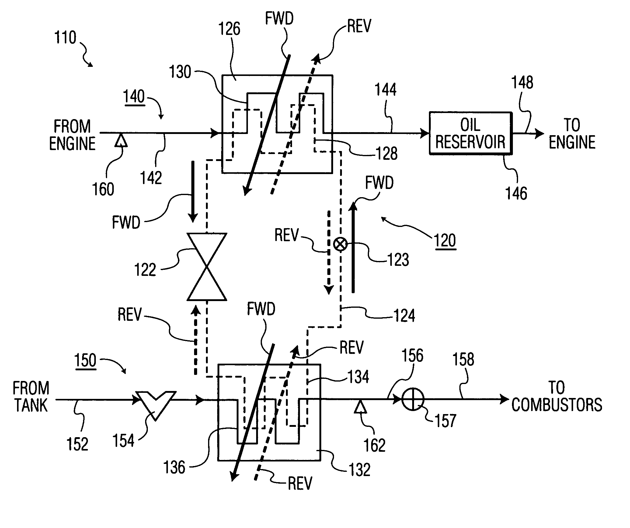
[0032]FIG. 4 is a schematic depiction of the invention incorporating a basic building block of a thermal management system according to the present invention. This basic building block comprises a heat transfer control module with a reversible heat pump that circulates a working fluid through at least two heat exchangers. This module can be included in myriad thermal management systems to optimize thermal management for particular apparatus such as gas turbine aircraft engines like those described above in connection with FIGS. 1 to 3. By employing a reversible heat pump, the present invention provides significantly improved operational flexibility that enables the heat transfer characteristics of the system to be more precisely controlled and more readily tailored to a particular engine across a greater range of operating conditions. When used in combination with a reservoir for a lubricant that circulates through the apparatus, as described below, the system includes a thermal cap...

second embodiment

[0045]FIG. 5 illustrates a thermal management system 210 according to the invention, in which a heat transfer control module 220 is used in cooperation with a conventional fuel re-circulation system such as the one depicted in FIG. 2. In the embodiment shown in FIG. 5, components that represent counterparts of components shown in FIG. 4 are given a “200” series reference number. In that same regard, components in FIG. 5 are constructed and operate in a fashion similar to corresponding components in FIG. 4, as described in detail above. Accordingly, one skilled in this art will readily understand the construction and operational principles of the heat transfer control module 220 in FIG. 5 by reference to the description above in connection with FIG. 4, and for that reason the following description focuses mainly on the differences between the systems shown in FIGS. 4 and 5.

embodiment 210

[0046]A basic difference between the thermal management system 110 shown in FIG. 4 and its counterpart embodiment 210 shown in FIG. 5 is that the fuel exit line 256 from the second heat exchanger 232 leads to a fuel recirculation subsystem 280, and more particularly to a fuel re-circulation valve 282 of the fuel recirculation subsystem. The valve 282 corresponds to the valve RCV shown in FIG. 2. One output of the valve is an exit fuel line 284 that leads to a fuel control valve 257, from which an engine fuel line 258 supplies fuel to the engine combustors. A second outlet of the valve 282 leads to a fuel recirculation line 286. The fuel recirculation line 286 is introduced to an auxiliary heat exchanger 288 with a first heat exchange path 290 for the fuel, the outlet of which re-introduces the fuel to the engine fuel tank. A second heat exchange path 292 accepts a small portion of the inlet or nacelle air flow, as described in connection with the systems depicted in FIG. 2. More par...


PUM


Abstract

A thermal management system for a gas turbine powerplant with an engine oil line and an engine fuel line incorporates a heat transfer control module that includes a reversible heat pump with a heat pump compressor for circulating working fluid in forward and reverse directions through a working fluid line of the heat pump. The heat control module also includes a first heat exchanger having a heat exchange path for the working fluid between the compressor and a heat pump expansion valve and another heat exchange path for the engine oil. A second heat exchanger has a heat exchange path for the working fluid between the compressor and the expansion valve and another heat exchange path for the engine fuel. The heat pump can be operated in forward or reverse directions depending on whether heat is to be transferred from the engine oil or the fuel to the heat pump working fluid. In another embodiment an engine oil reservoir located between the first heat exchanger and the engine collects the oil before it is introduced to the engine and thus acts as a heat capacitor for the system.

Description

BACKGROUND OF THE INVENTION[0001]1. Field of the Invention[0002]The present invention relates to systems and methods for controlling temperatures of fluids in powerplants, and more particularly, to thermal management systems and methods for controlling fuel and lubricant temperatures in gas turbine engines.[0003]2. Description of Related Art[0004]Gas turbine engines, particularly aircraft powerplants, conventionally use engine fuel as a heat sink to cool electric and electronic components such as engine control systems and / or to cool liquids within the engine such as the engine lubricant and hydraulic fluids for engine control and actuation systems. U.S. Pat. No. 2,865,580, No. 3,080,716 and No. 3,779,007 describe examples of these types of cooling systems. Aircraft also conventionally use engine fuel as a heat sink to cool aircraft components like avionics and / or to cool liquids within the aircraft such as gearbox or generator lubricants and hydraulic fluids for aircraft control an...

Claims


Application Information

Patent Timeline
Patent Type & Authority Patents(United States)
IPC IPC(8): F02K99/00
CPCF02C7/14F02C7/224Y02T50/671Y02T50/675Y02T50/60
Inventor SMITH, J. WALTER
Owner PROPULSION GAS TURBINE & ENERGY EVALUATIONS
Why Eureka
Try Eureka