Control device for internal combustion engine

a control device and internal combustion engine technology, applied in the direction of electric control, combustion engines, machines/engines, etc., can solve the problems of significant air-fuel ratio difference between the most downstream cylinders, degrade driving performance and emissions performance, and reduce the effect of emissions

Inactive Publication Date: 2012-05-03
TOYOTA JIDOSHA KK
View PDF4 Cites 29 Cited by
  • Summary
  • Abstract
  • Description
  • Claims
  • Application Information

AI Technical Summary

Benefits of technology

[0010]The present invention has been made in view of the above circumstances. An object of the present invention is to avoid an air-fuel ratio difference between cylin

Problems solved by technology

In such an instance, however, there arises the following problem.
Thus, there arises a significant air-fuel ratio differenc

Method used


Image

  • Control device for internal combustion engine
  • Control device for internal combustion engine
  • Control device for internal combustion engine

Examples


first embodiment

[0024]A first embodiment of the present invention will now be described with reference to FIGS. 1 to 4.

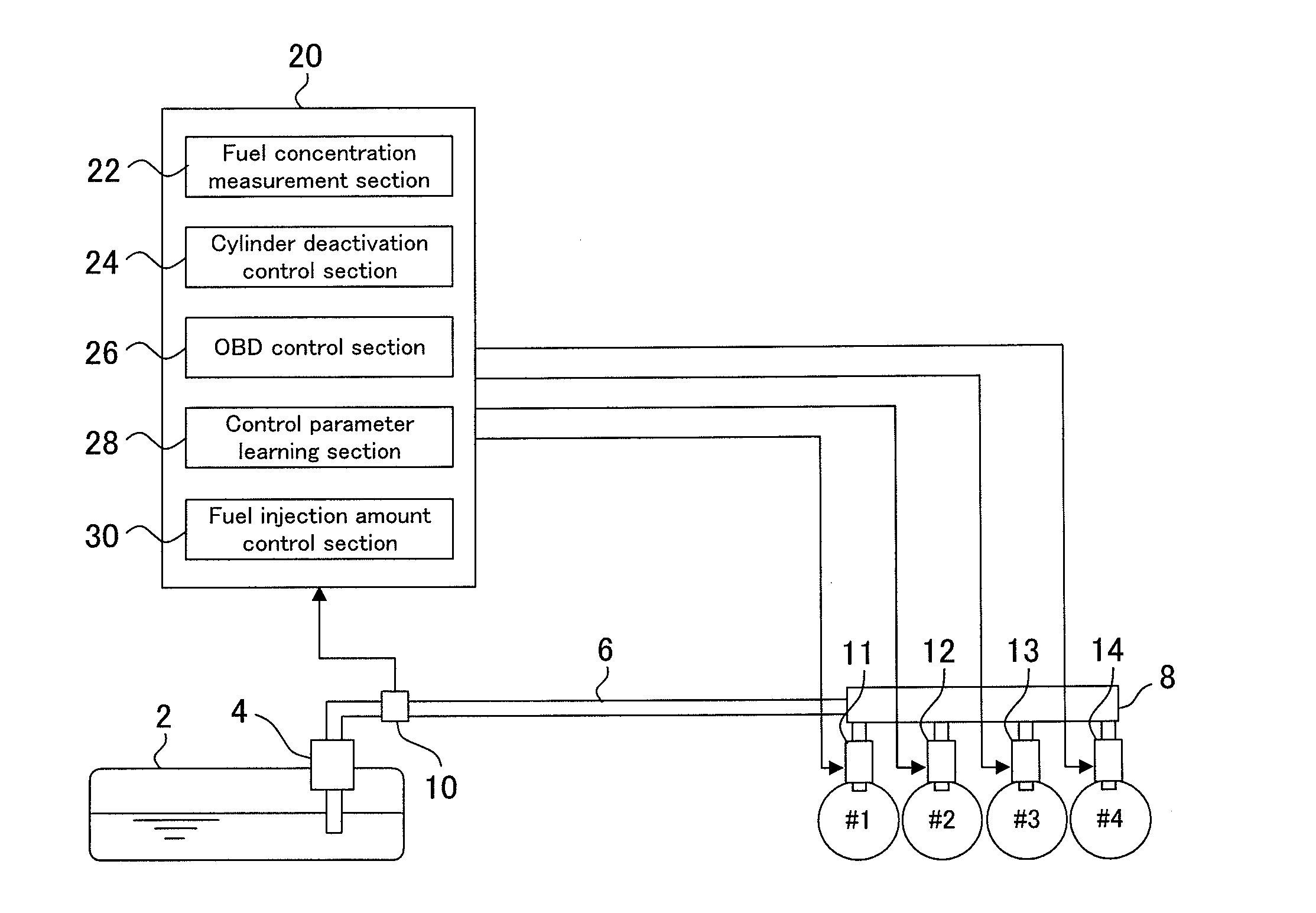
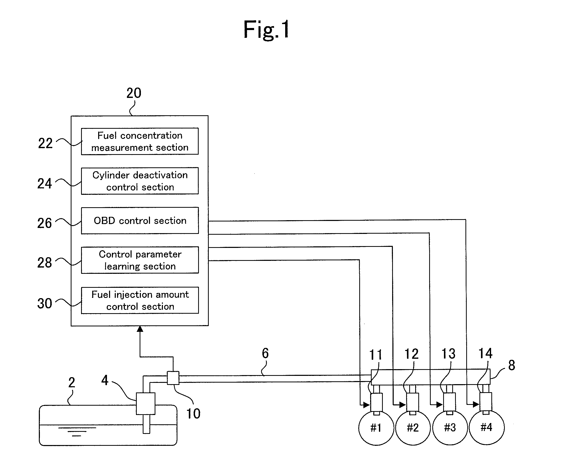
[0025]A control device according to the first embodiment is applied to an FFV internal combustion engine that can use not only gasoline but also biofuel-blended gasoline. FIG. 1 is a schematic diagram illustrating the configuration of a fuel supply system for such an internal combustion engine.

[0026]The fuel supply system shown in FIG. 1 is configured so that a fuel line 6 is connected between a fuel tank 2 and a delivery pipe 8. The fuel line 6 is connected to one end of the delivery pipe 8. From an inlet to a rear end, four injectors 11, 12, 13, and 14 are sequentially arranged and connected to the delivery pipe 8. The internal combustion engine used in the present embodiment is an in-line four-cylinder engine. The numerals #1, #2, #3, and #4 in FIG. 1 are cylinder numbers. A fuel pump 4 is attached to a fuel tank 2 side end of the fuel line 6. The fuel pump 4 draws fuel from the...

second embodiment

[0060]A second embodiment of the present invention will now be described with reference to FIG. 5.

[0061]The control device according to the second embodiment is applied to an internal combustion engine having the fuel supply system shown in FIG. 1, as is the case with the control device according to the first embodiment. Therefore, the following description is based on the system shown in FIG. 1, as is the case with the first embodiment.

[0062]The second embodiment differs from the first embodiment in the functionality of the fuel injection amount control section 30. More specifically, these two embodiments differ in the method of estimating the injected fuel concentration in each cylinder although are similar to each other in that they control the fuel injection amount on an individual cylinder basis. A routine shown in a flowchart of FIG. 5 is used by the fuel injection amount control section 30 to calculate a cylinder-specific injected fuel concentration. This cylinder-specific in...


PUM


Abstract

An object of the present invention is to avoid an air-fuel ratio difference between cylinders upon recovery from a cylinder deactivation in a situation where some of a plurality of cylinders of an internal combustion engine capable of using a plurality of types of fuels having different properties are to be deactivated upon the halt of fuel injection from an injector.
To accomplish the object, a control device to which the present invention is applied includes a fuel property sensor that is installed in a fuel line between a fuel tank and a delivery pipe, and detects a fuel property change from a change in a signal of the fuel property sensor. Upon detection of a fuel property change, the control device prohibits the deactivation of a cylinder before the completion of a fuel property change in the delivery pipe.

Description

TECHNICAL FIELD [0001]The present invention relates to a control device for an internal combustion engine that is capable of using a plurality of types of fuels having different properties. More specifically, the present invention relates to an internal combustion engine control device having a cylinder deactivation function that deactivates some of a plurality of cylinders.BACKGROUND ART [0002]An internal combustion engine capable of using fuels having different properties is mounted in a so-called FFV (flexible-fuel vehicle). An example of such an FFV internal combustion engine described, for instance, in JP-A-2006-322401 is capable of using gasoline and alcohol. When fuels having different properties are to be used, an air-fuel ratio needs to be adjusted in accordance with fuel properties. When, for instance, alcohol-blended gasoline is used as fuel, it is necessary to adjust the air-fuel ratio in accordance with the concentration of alcohol in the fuel because the alcohol greatl...

Claims


Application Information

Patent Timeline
IPC IPC(8): F02D19/06F02D17/00
CPCF02D17/02F02D19/024F02D19/084F02D19/087Y02T10/32F02D41/0087F02D2200/0611Y02T10/36F02D41/0025Y02T10/30
Inventor SASAI, MIEWAKAO, KAZUHIRO
Owner TOYOTA JIDOSHA KK
Why Eureka
Try Eureka