
Display device and bottom chassis thereof

a technology which is applied in the direction of identification means, instruments, optics, etc., can solve the problems of increasing production costs of difficulty in assembling conventional display device and bottom chassis thereof, so as to reduce production costs and facilitate assembly of optical members. , the effect of small siz

Inactive Publication Date: 2009-11-26
SAMSUNG ELECTRONICS CO LTD
View PDF29 Cites 30 Cited by
  • Summary
  • Abstract
  • Description
  • Claims
  • Application Information

AI Technical Summary

Benefits of technology

[0012]The present general inventive concept provides a display device, which includes separable supporters having a smaller size than that of a conventional middle bezel to reduce production costs and to easily assemble optical members to a bottom chassis, and a bottom chassis thereof.
[0013]The present general inventive concept also provides a display device to prevent a difference between light and darkness on optical members due to lightening only specific regions of optical members by light reflected by an optical member fixing unit, and a bottom chassis thereof.
[0014]The present general inventive concept also provides a bottom chassis, which has excellent physical characteristics, such as a thermal expansion rate, strength, and a injection molding property.

Problems solved by technology

However, in the conventional display device and the bottom chassis thereof, the middle bezel connected to the bottom chassis has the shape of a rectangular frame, and thus increases production costs of the display device and the bottom chassis thereof.
Further, since the optical members are fixed using the middle bezel after the optical members are located to the connection portion of the bottom chassis, assembling the conventional display device and the bottom chassis thereof is not easy.

Method used


Image

  • Display device and bottom chassis thereof
  • Display device and bottom chassis thereof
  • Display device and bottom chassis thereof

Examples


Embodiment Construction

[0046]Reference will now be made in detail to embodiments of the present general inventive concept, an example of which is illustrated in the accompanying drawings, wherein like reference numerals refer to like elements throughout. The embodiments are described below to explain the present general inventive concept by referring to the annexed drawings.

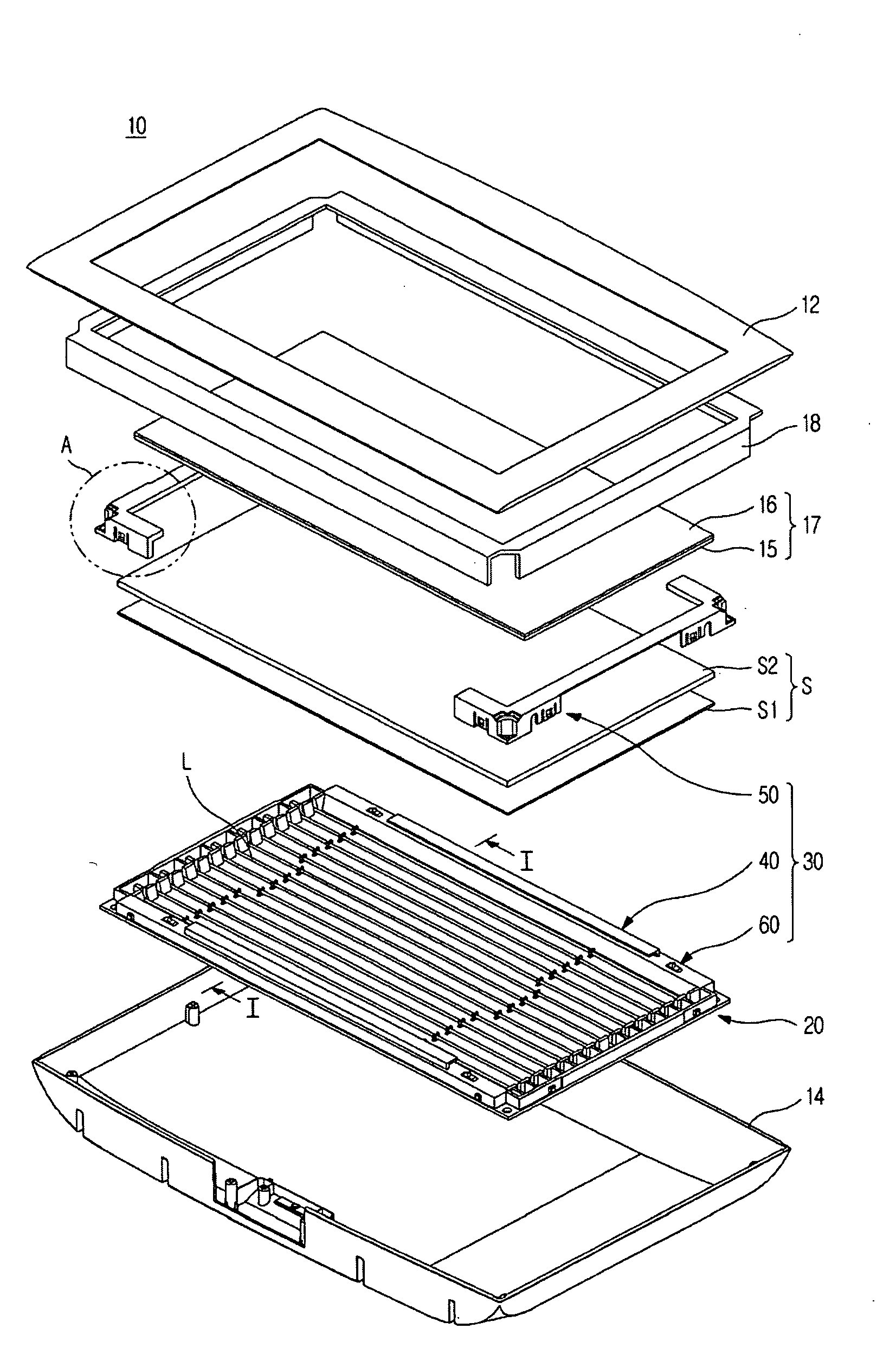
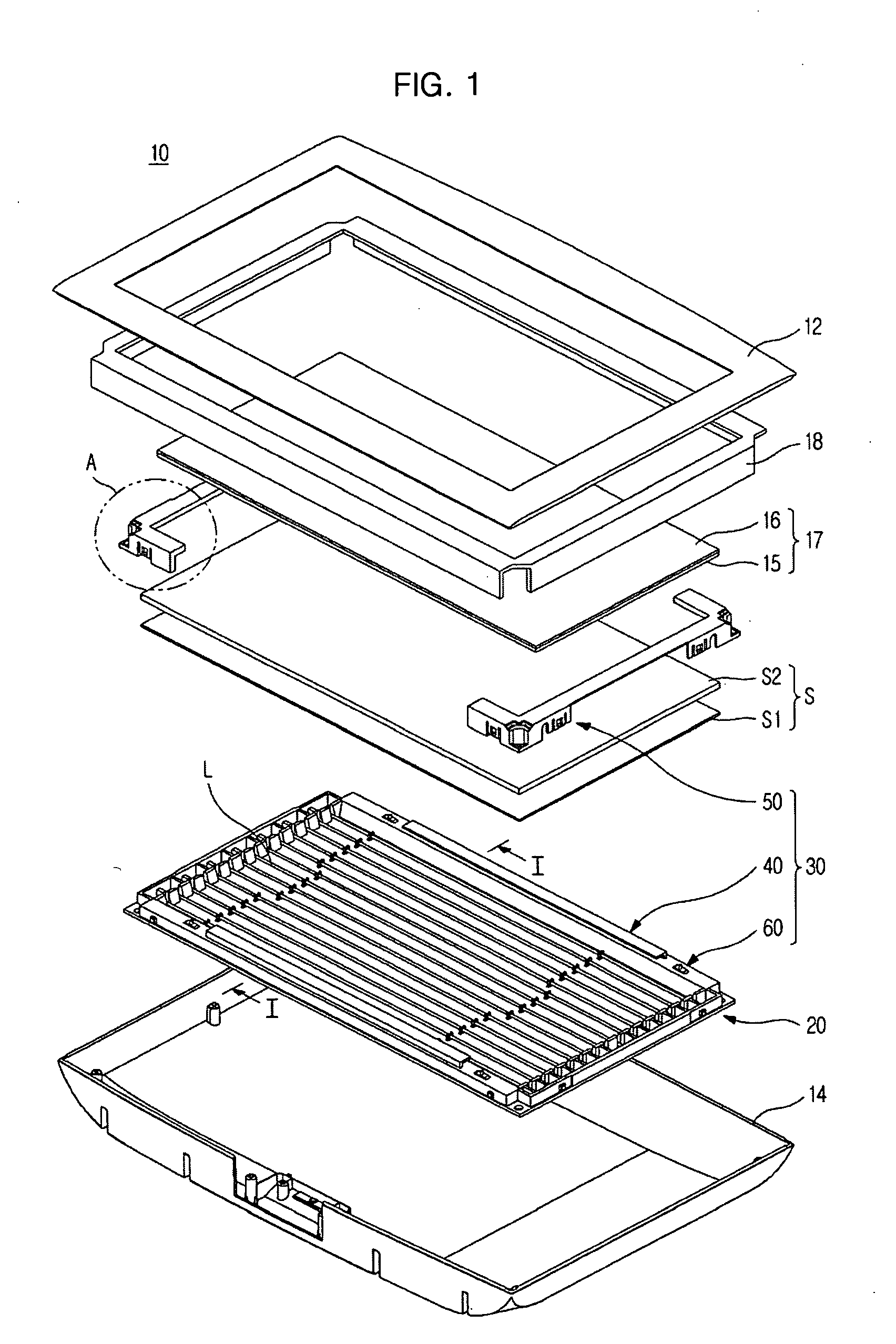
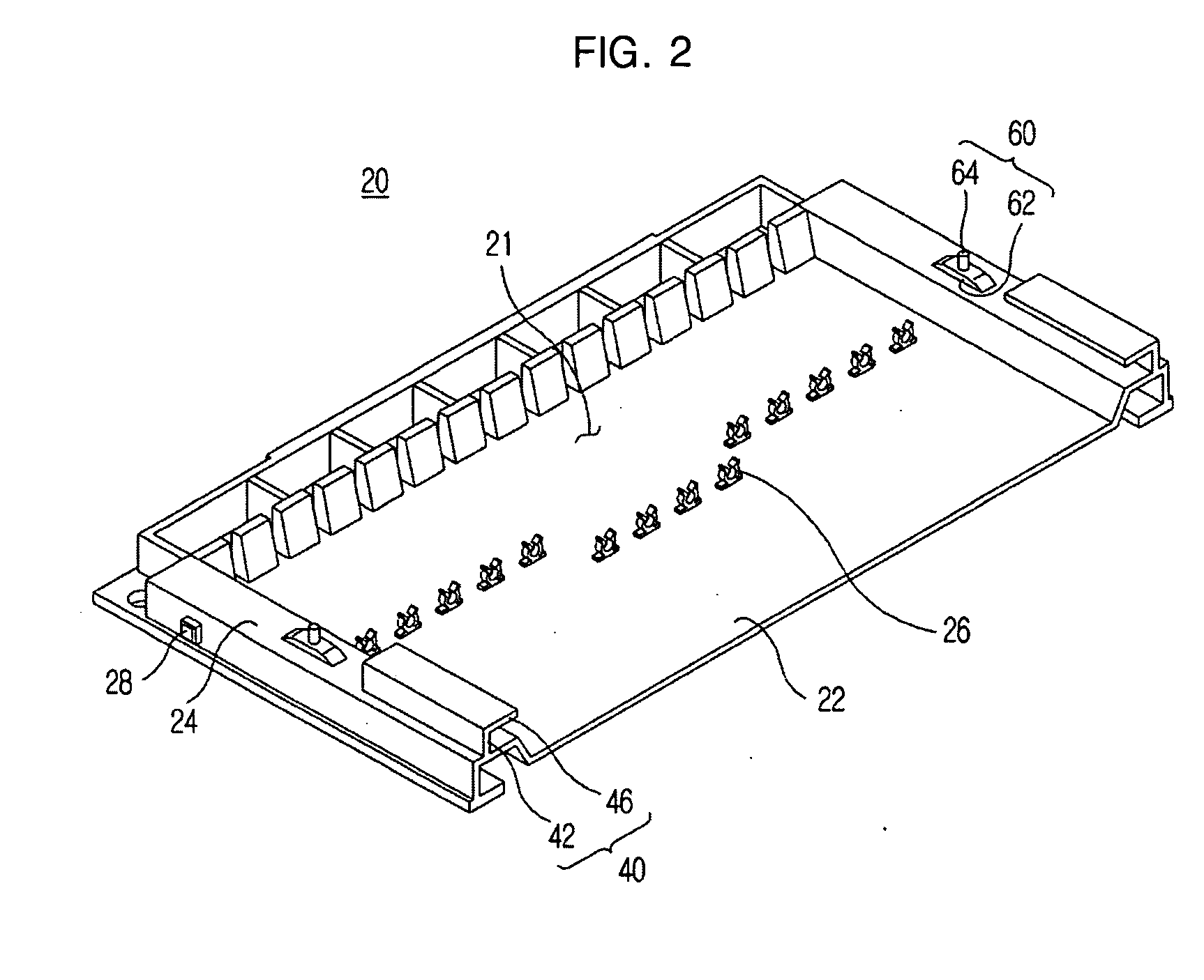
[0047]FIG. 1 is an exploded perspective view illustrating a display device in accordance with an embodiment of the present general inventive concept, FIG. 2 is a perspective view illustrating a bottom chassis of FIG. 1, taken along the line I-I, and FIG. 3 is an enlarged view of a portion ‘A’ of a separable supporter of FIG. 1.

[0048]As illustrated in FIGS. 1 to 3, a display device 10 in accordance with the embodiment illustrated in FIG. 1 includes front and rear covers 12 and 14, a display panel 17, a top chassis 18, a bottom chassis 20, optical members S connected to an opening 21 of the bottom chassis 20, and an optical member fixing...


PUM


Abstract

A display device, which has a bottom chassis provided with an opening formed at one side thereof and receiving light sources therein, and at least one optical member connected to the opening to enhance optical characteristics of light emitted from the light sources, includes an optical member fixing unit including integral supporters formed integrally with the bottom chassis; and separable supporters connected to the bottom chassis to prevent movement of the at least one optical member connected to the integral supporters. The display device allows the separable supporters to have a smaller size than that of a conventional middle bezel, thus reducing production costs and to easily assemble the at least one optical member to the bottom chassis.

Description

CROSS-REFERENCE TO RELATED APPLICATIONS[0001]This application claims priority under 35 U.S.C. §119(a) from Korean Patent Application No. 2008-0046923, filed May 21, 2008, in the Korean Intellectual Property Office, the disclosure of which is incorporated herein in its entirety by reference.BACKGROUND OF THE INVENTION[0002]1. Field of the Invention[0003]The present general inventive concept relates to a display device and a bottom chassis thereof, and more particularly, to a display device, in which separable supporters have a smaller size than that of a conventional middle bezel to reduce production costs and optical members are easily assembled with a bottom chassis compared with a case of using a separate middle bezel, and a bottom chassis thereof.[0004]2. Description of the Related Art[0005]In general, display devices, which are widely used, are divided into an emissive type and a non-emissive or passive type. Emissive-type display devices refers to display devices, which can emi...

Claims


Application Information

Patent Timeline
IPC IPC(8): G09G3/36
CPCG02F1/133308G02F1/133603G02F1/133604G02F1/133605G02F1/133608G02F2201/465G02F2001/133314G02F2001/133322G02F2001/133325G02F2001/133328G02F1/133611G09F9/30G02F1/133314G02F1/133322G02F1/133325G02F1/133328G02F1/1333
Inventor BYOUN, DAE HYOUNKIM, SEUNG BUMAN, JAN SEOK
Owner SAMSUNG ELECTRONICS CO LTD
Learn More