Polyimide film

a polyimide film and film technology, applied in the field of polyimide film, can solve the problems of low signal strength, limited application field, low signal strength, etc., and achieve the effects of low loss, good rise of pulse signals, and fast response speed

Active Publication Date: 2007-11-29
TOYO TOYOBO CO LTD
View PDF3 Cites 29 Cited by
  • Summary
  • Abstract
  • Description
  • Claims
  • Application Information

AI Technical Summary

Benefits of technology

[0021] The polyimide film of the present invention shows lower loss and faster response speed (good rise of pulse signals) at high frequency as compared to conventionally known polyimide films. Therefore, a circuit comprising the polyimide film of the present invention is expected to operate at a higher speed. In addition, it simultaneously has higher rigidity, strength and heat resistance than those of conventional polyimide films. Therefore, the film is preferably used for high frequency electronics and other electronics, and is useful as a substrate film for the production of copper-adhered substrates for flexible print circuit (FPC) with high size precision requirements, a carrier tape for tape automated bonding (TAB) and the like.
[0022] According to the present invention, for example, the difference in the surface planar orientation degree between the front and the back of the polyimide film is r

Problems solved by technology

However, ceramic is not flexible and cannot be made thin, which limits its applicable field.
On the other hand, problems of low signal strength, delay in signal transmission and the like are of concern in the application to high frequency signals.
While the film made of polytetrafluoroethylene is also compatible with high frequency, it is associated with problems in that the film cannot be made thin due to low elastic modulus, the film shows poor adhesion to a metal conductor, a resistor and the like on the surface, the film is unsuitable for the production of ultrafine wiring circuits due to its high coefficient of linear thermal expansion which causes marked dimensional changes due to temperature change, and the like.
As a result, its applicable field is limited.
As the situation stands, a fil

Method used


Image

  • Polyimide film
  • Polyimide film
  • Polyimide film

Examples


examples

[0106] The effectiveness of the present invention is explained in the following by referring to Examples, which are not to be construed as limitative. In the following Examples, the evaluation methods of the properties are as follows.

1. Reduced Viscosity (ηsp / C) of Polyamide Acid

[0107] A solution of a polymer in N-methyl-2-pyrrolidone to a polymer concentration of 0.2 g / dl was measured with a Uberode type viscosity tube at 30° C.

2. Film Thickness of Polyimide Film

[0108] The film thickness was measured with a micrometer (Millitron (R)1245D, manufactured by Finepruf).

3. Tensile Elastic Modulus, Tensile Strength at Break and Tensile Elongation at Break of Polyimide Film

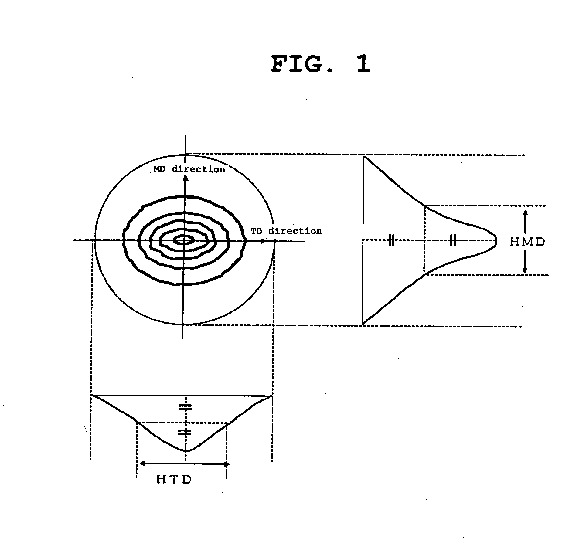
[0109] A film after drying was cut out in the longitudinal direction (MD direction) and transverse direction (TD direction) to give a reed-shaped strip (length 100 mm, width 10 mm) as a test piece, which was subjected to the measurement of tensile elastic modulus, tensile strength at break and tensile elongation...

examples 1-4

, Comparative Examples 1-3

Production Example of Polyamide Acid Solution—1

[0177] A reaction container equipped with a nitrogen inlet tube, a thermometer and a stirring rod was purged with nitrogen, and 500 parts by mass of 5-amino-2-(p-aminophenyl)benzoxazole was placed therein. Then, 9000 parts by mass of N-methyl-2-pyrrolidone was added and, after complete dissolution, 485 parts by mass of pyromellitic acid dianhydride was added. The mixture was stirred at 25° C. for 50 hr to give a brown viscous polyamide acid solution. The reduced viscosity (ηsp / C) was 4.6 dl / g.

Production Example of Film—1

[0178] The polyamide acid solution was applied to a stainless belt (squeegee / belt gap was 650 μm) and dried at 90° C. for 60 min. After drying, a self-supporting polyamide acid film was peeled off from a stainless belt to give a green film having a thickness of 40 μm.

[0179] The obtained green film was passed through a nitrogen purged continuous type heat treatment furnace, and heated in two ...

example 5

Production Example of Polyamide Acid Solution—2

[0180] A reaction container equipped with a nitrogen inlet tube, a thermometer and a stirring rod was purged with nitrogen, and 5-amino-2-(p-aminophenyl)benzoxazole (formula 1, 450 parts by mass) and 5-amino-2-(m-aminophenyl)benzoxazole (formula 3, 50 parts by mass) were placed therein. Then, 9100 parts by mass of N,N-dimethylacetamide was added and, after complete dissolution, 485 parts by mass of pyromellitic acid dianhydride was added. The mixture was stirred at 25° C. for 40 hr to give a brown viscous polyamide acid solution A. The ηsp / C thereof was 4.0 dl / g.

Production Example of Film—2

[0181] The polyamide acid solution was applied to a stainless belt (squeegee / belt gap was 650 μm) and dried at 90° C. for 60 min. After drying, a self-supporting polyamide acid film was released from a stainless belt to give a green film having a thickness of 40 μm. The amount of the residual solvent in the green film then was 35% by mass.

[0182] T...


PUM

PropertyMeasurementUnit
Temperatureaaaaaaaaaa

Abstract

This polyimide film is superior in heat resistance, rigidity and high frequency properties, is free of inconveniences due to curling even when various functional layers are laminated by heating, and is preferable as a substrate film superior in thermal degradation stability for electronic parts. This polyimide film has a planar orientation coefficient of 0.79-0.89 as measured by an X-ray diffraction method, a difference in the surface planar orientation degree between one surface thereof and the other surface thereof of not more than 2 and a curling degree of not more than 5%, which is obtained by imidation of a polyimide precursor film having a particular imidation rate.

Description

REFERENCE TO RELATED APPLICATION [0001] This application is a national stage application under 35 USC 371 of International Application No. PCT / JP2004 / 019528, filed Dec. 27, 2004. TECHNICAL FIELD [0002] The present invention relates to a polyimide film, particularly, a polyimide film preferable as a substrate for high frequency-matching electrical parts and superior in heat resistance. BACKGROUND ART [0003] As a material for substrates for electrical parts of information and telecommunication devices (broadcast devices, mobile radio, portable telecommunication devices etc.), radar, highspeed information processing devices and the like, ceramic has been conventionally used. Substrates made of ceramic have heat resistance and can also be used for recent information telecommunication devices having a high frequency signal band (reaching the GHz band). However, ceramic is not flexible and cannot be made thin, which limits its applicable field. [0004] Accordingly, consideration has been m...

Claims


Application Information

Patent Timeline
IPC IPC(8): C08J5/18C08G73/22C08L79/04H05K1/03
CPCC08J5/18H05K1/0346C08J2379/08C08G73/1067C08L79/08C08L2203/16C08L2201/02
Inventor TSUTSUMI, MASAYUKIMAEDA, SATOSHIKAWAHARA, KEIZOYOSHIDA, TAKEFUMIOKAMOTO, KAZUTAKEMORINO, MORIOUEMURA, SHOICHINAGARA, AKINOBUTAKAHASHI, NORIKOOYAMA, HIROKOKURAHARA, SHUNJIYASUI, JUN
Owner TOYO TOYOBO CO LTD
Why Eureka
Try Eureka