Device for converting kinetic energy of liquid into mechanical energy

A kinetic energy conversion and mechanical energy technology, applied in mechanical equipment, machines/engines, circulating chain machinery, etc., can solve the problems of converting kinetic energy of water flow into mechanical energy, difficulties, etc.

Inactive Publication Date: 2013-04-03
侯叶权
View PDF5 Cites 4 Cited by
  • Summary
  • Abstract
  • Description
  • Claims
  • Application Information

AI Technical Summary

Problems solved by technology

[0002] At present, existing energy conversion devices, such as power generation devices, generally convert wind energy or water energy into mechanical energy through a large drive impeller, especially when using water energy to convert mechanical energy, the required potential energy needs to be It is realiz

Method used


Image

  • Device for converting kinetic energy of liquid into mechanical energy
  • Device for converting kinetic energy of liquid into mechanical energy
  • Device for converting kinetic energy of liquid into mechanical energy

Examples


Embodiment 1

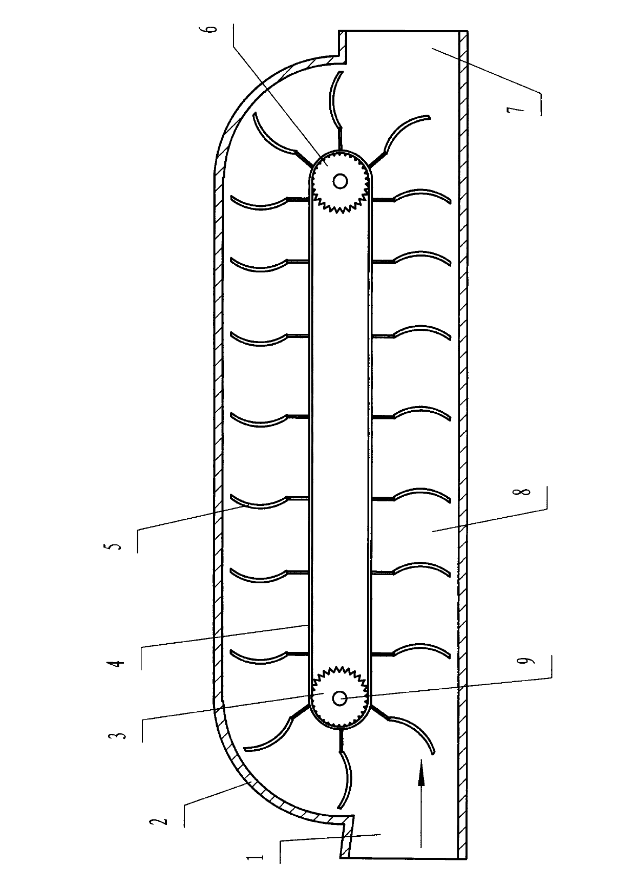
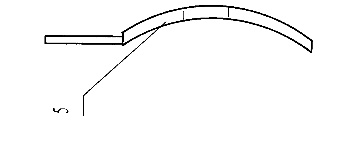
[0015] Embodiment 1: with reference to attached Figure 1~3 , including a housing 2, the housing 2 is "tank crawler-shaped", one end of the housing 2 is provided with a liquid inlet 1, the other end of the housing 2 is provided with a liquid outlet 7, and the housing 2 is provided with a flow channel 9 and a liquid driving device, the liquid driving device is composed of a driving wheel 3, a power output shaft 8, a driven wheel 6, a transmission chain belt 4, and a vane 5, and the driving wheel 3 is located at the liquid inlet 1, The power output shaft 8 is arranged on the driving wheel 3 shaft, the driven wheel 6 is arranged at the liquid outlet 7, the driving wheel 3 is provided with transmission gear teeth, and the transmission chain belt 4 is arranged on the driving wheel 3 and the driven wheel 6 , the transmission gear teeth on the driving wheel 3 mesh with the transmission chain belt 4, and the driven wheel 6 is a smooth runner, so that the transmission chain belt 4 can ...

Embodiment 2

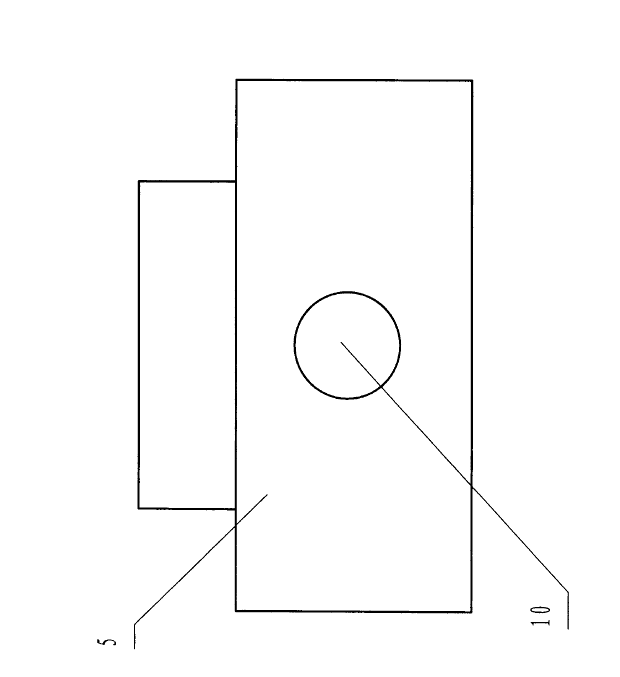
[0016] Embodiment 2: Compared with Embodiment 1, the difference lies in that the area of ​​the said perforation 10 accounts for 22% of the surface area of ​​the blade, and two are provided.

Embodiment 3

[0017] Embodiment 3: Compared with Embodiment 1, the difference is that the area of ​​the said perforation 10 accounts for 30% of the surface area of ​​the blade, and three are provided.


PUM


Abstract

The invention relates to a device for converting kinetic energy of a liquid into mechanical energy. The device is characterized by comprising a shell, wherein the shell is tank track-shaped; a liquid inlet is formed at one end of the shell; a liquid outlet is formed at the other end of the shell; a liquid runner and a liquid driving device are arranged in the shell; the liquid driving device comprises a driving wheel, a power output shaft, a driven wheel, a transmission chain belt and an impeller plate; the driving wheel is arranged in the liquid inlet; the power output shaft is arranged on a driving wheel axle; the driven wheel is arranged in the liquid outlet; transmission wheel teeth are arranged on the driving wheel; the transmission chain belt is arranged on the driving wheel and the driven wheel; the transmission wheel teeth on the driving wheel are engaged with the transmission chain belt; the impeller plate is arranged on the transmission chain belt; and a through hole is formed in the impeller plate. According to the invention, a problem that the flowing energy of the liquid with small fall can be output through being converted into transmission force is solved.

Description

technical field [0001] The invention relates to a device for converting liquid kinetic energy into mechanical energy. Background technique [0002] At present, existing energy conversion devices, such as power generation devices, generally convert wind energy or water energy into mechanical energy through a large drive impeller, especially when using water energy to convert mechanical energy, the required potential energy needs to be It is realized by using the characteristics of large water flow potential energy drop. Compared with some river water or canal water with small water flow drop, it is difficult to convert the kinetic energy of water flow into mechanical energy, and it is also very difficult to use water kinetic energy to generate electricity. Contents of the invention [0003] The object of the present invention is to provide a device for converting liquid kinetic energy into mechanical energy. [0004] The purpose of the present invention is achieved through...

Claims


Application Information

Patent Timeline
IPC IPC(8): F03B9/00
CPCY02E10/20
Inventor 侯叶权温峻
Owner 侯叶权
Why Eureka
Try Eureka