Centrifugal compressor

A centrifugal compressor, compressor technology, applied in the direction of mechanical equipment, machine/engine, liquid fuel engine, etc., can solve the problems of mechanical loss, large volume, high cost, etc., achieve light weight, small overall shape, avoid mechanical loss and noise effect

Active Publication Date: 2013-04-03
GREE ELECTRIC APPLIANCES INC
View PDF6 Cites 13 Cited by
  • Summary
  • Abstract
  • Description
  • Claims
  • Application Information

AI Technical Summary

Problems solved by technology

[0004] The present invention aims to provide a centrifugal compressor to solve the problems of mechanical loss, high noise, large volume and high cost of the prior art centrifugal compressor

Method used


Image

  • Centrifugal compressor
  • Centrifugal compressor
  • Centrifugal compressor

Examples


Embodiment Construction

[0024] The embodiments of the present invention will be described in detail below with reference to the accompanying drawings, but the present invention can be implemented in many different ways defined and covered by the claims.

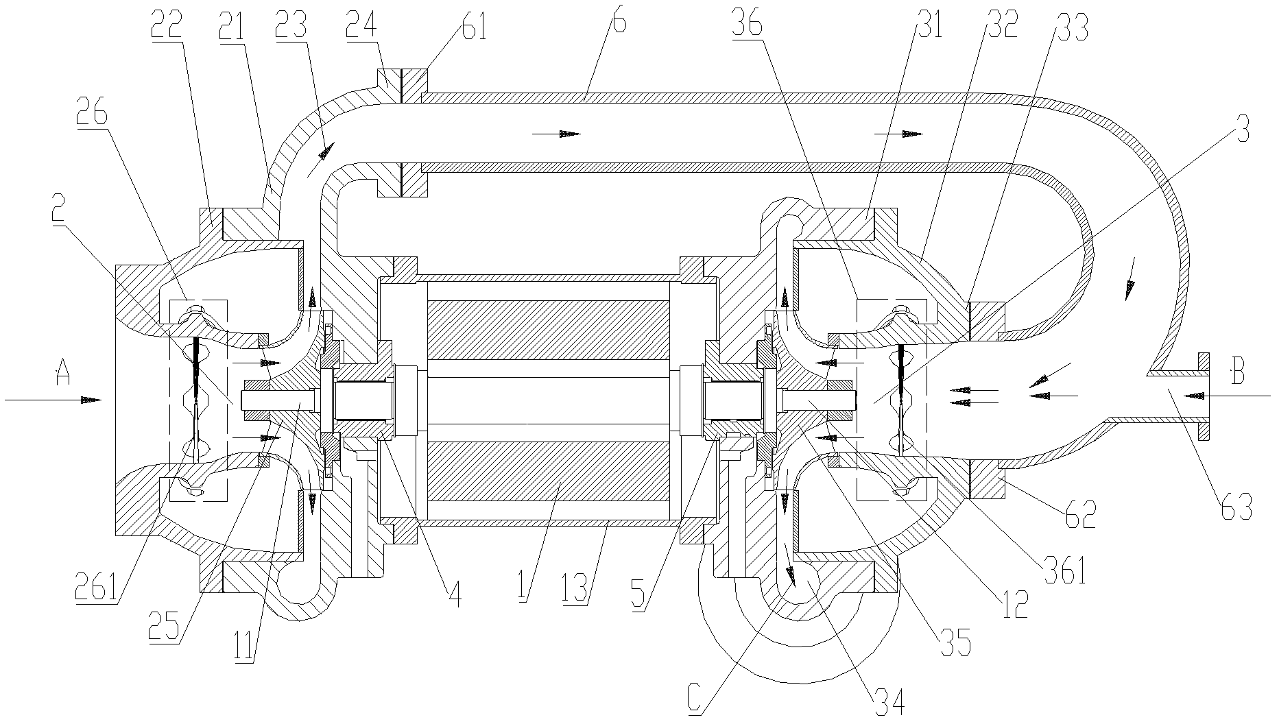
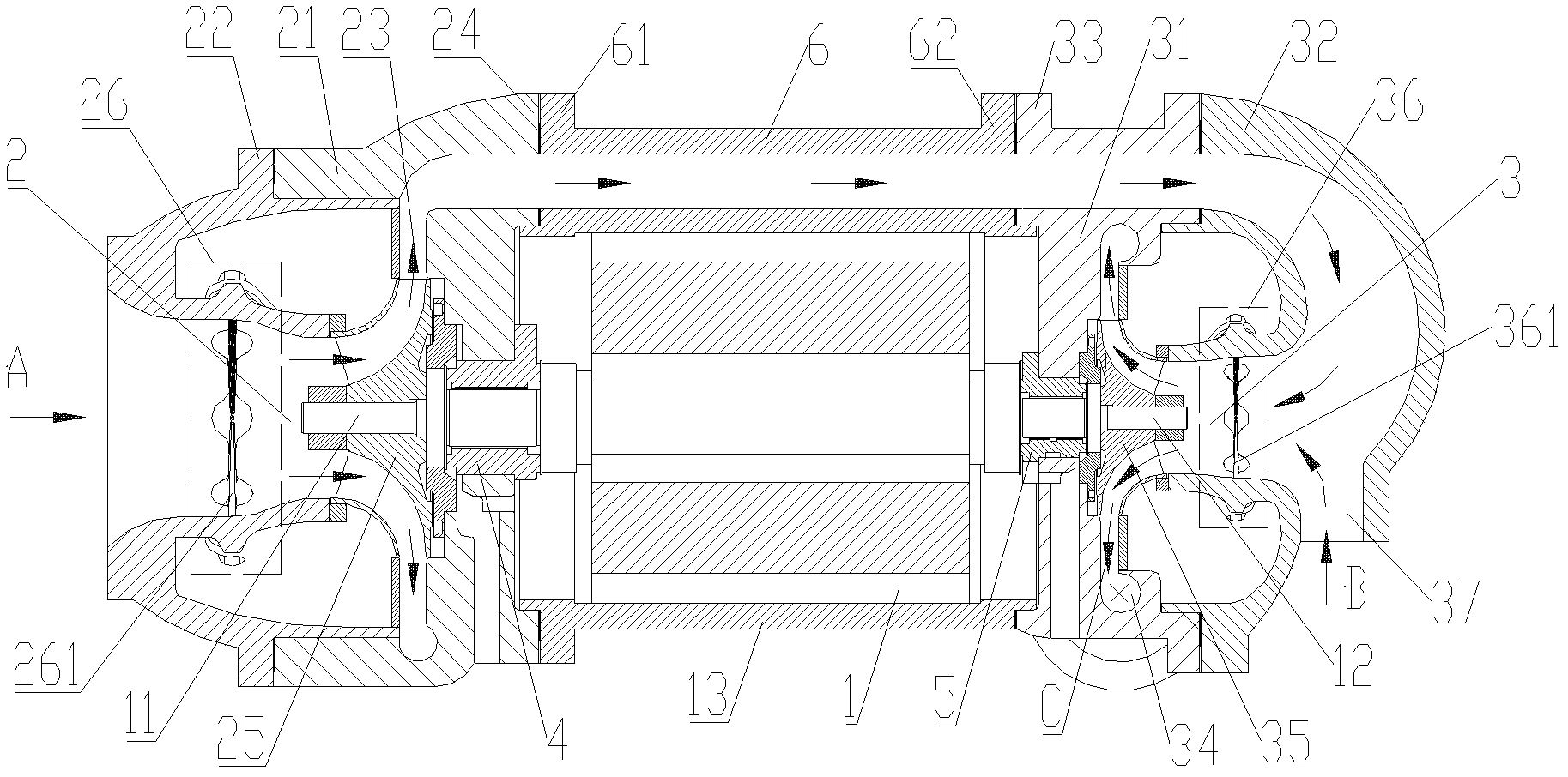
[0025] Such as Figure 1-2 As shown, the centrifugal compressor in the present invention includes: a motor 1, a first compressor 2 and a second compressor 3; wherein, the motor 1 includes a cylinder 13, a first output end 11 and a second output end 12, and the cylinder 13 has a first end and a second end oppositely arranged, and the first output end 11 and the second output end 12 are respectively arranged at the first end and the second end; the first compressor 2 is installed on the first output end 11 of the motor 1 ; The second compressor 3 is installed on the second output end 12 of the motor 1 ; the outlet 24 of the first compressor 2 communicates with the inlet 33 of the second compressor 3 . Preferably, the motor 1 is a DC frequency convers...


PUM


Abstract

The invention provides a centrifugal compressor. The centrifugal compressor comprises a motor, a first compressor and a second compressor, wherein the motor comprises a cylinder body, a first output end and a second output end; the cylinder body is provided with a first end and a second end which are oppositely arranged; the first output end and the second output end are respectively arranged at the first end and the second end; the first compressor is arranged at the first output end of the motor; the second compressor is arranged at the second output end of the motor; and an outlet of the first compressor is communicated with an inlet of the second compressor. The centrifugal compressor directly drives impellers of the first compressor and the second compressor to rotate at high speed, so that a gear speed-increasing structure is eliminated, the centrifugal compressor has the characteristics of small size and light weight, meanwhile, mechanical loss and noise caused in a driving process of the gear speed-increasing structure are also avoided, a sound isolating device for reducing the noise can also be eliminated, and the cost is reduced.

Description

technical field [0001] The invention relates to the field of air conditioners, and more specifically, to a centrifugal compressor. Background technique [0002] Centrifugal compressors in the field of air conditioning in the prior art usually use fixed-frequency AC motors or variable-frequency AC motors, and the speed is increased to the design speed through the speed-increasing gear to drive the impeller of the compressor to rotate, so that the high-speed rotating impeller does work on the incoming gas. , thereby increasing the gas pressure. [0003] This compressor structure in the prior art has the following disadvantages: (1) due to the use of speed-increasing gears, the mechanical loss of the centrifugal compressor is increased, thereby increasing the power consumption of the centrifugal compressor and affecting the centrifugal compressor. The performance of the unit; (2) The existence of the speed-increasing gear greatly increases the shape and structure of the centri...

Claims


Application Information

Patent Timeline
Patent Type & Authority Applications(China)
IPC IPC(8): F04D25/06F04D29/42F04D29/28
Inventor 刘华夏光辉张治平钟瑞兴蒋楠谢蓉蒋彩云傅鹏闫秀兵
Owner GREE ELECTRIC APPLIANCES INC
Why Eureka
Try Eureka