Pressure retaining valve with automatic water-drain pollution-discharge function

A technology of automatic drainage and pressure maintaining valves, applied in the direction of functional valves, safety valves, balance valves, etc., can solve the problems of unguaranteed water discharge efficiency, affecting the performance of the valve body assembly, hidden dangers of system reliability, etc., and achieve structural Simple, convenient maintenance and replacement, eliminating the effect of manual operation

Inactive Publication Date: 2013-04-03
DONGFENG AUTOMOBILE COMPANY
View PDF11 Cites 5 Cited by
  • Summary
  • Abstract
  • Description
  • Claims
  • Application Information

AI Technical Summary

Problems solved by technology

However, in actual use, due to the complex structure of the unloading valve, which is installed at the front end of the energy storage device, it is often infiltrated with high-temperature water vapor and oil, causing the internal parts to be easily damaged. The maintenance rate of the assembly and the failure rate of the function have always been high. It is troublesome to operate, and the water discharge efficiency cannot be guaranteed. During the use of the whole vehicle, the accumulated water in the energy storage device has not been discharged in time, which affects the performance of each valve body assembly arranged behind the energy storage device. There are certain hidden dangers in the reliability of the system

Method used


Image

  • Pressure retaining valve with automatic water-drain pollution-discharge function
  • Pressure retaining valve with automatic water-drain pollution-discharge function
  • Pressure retaining valve with automatic water-drain pollution-discharge function

Examples


Embodiment Construction

[0013] Below in conjunction with the arrangement of the technical solutions shown in the accompanying drawings, the present invention will be further described in detail, but the present invention is not limited to the arrangement of the technical solutions:

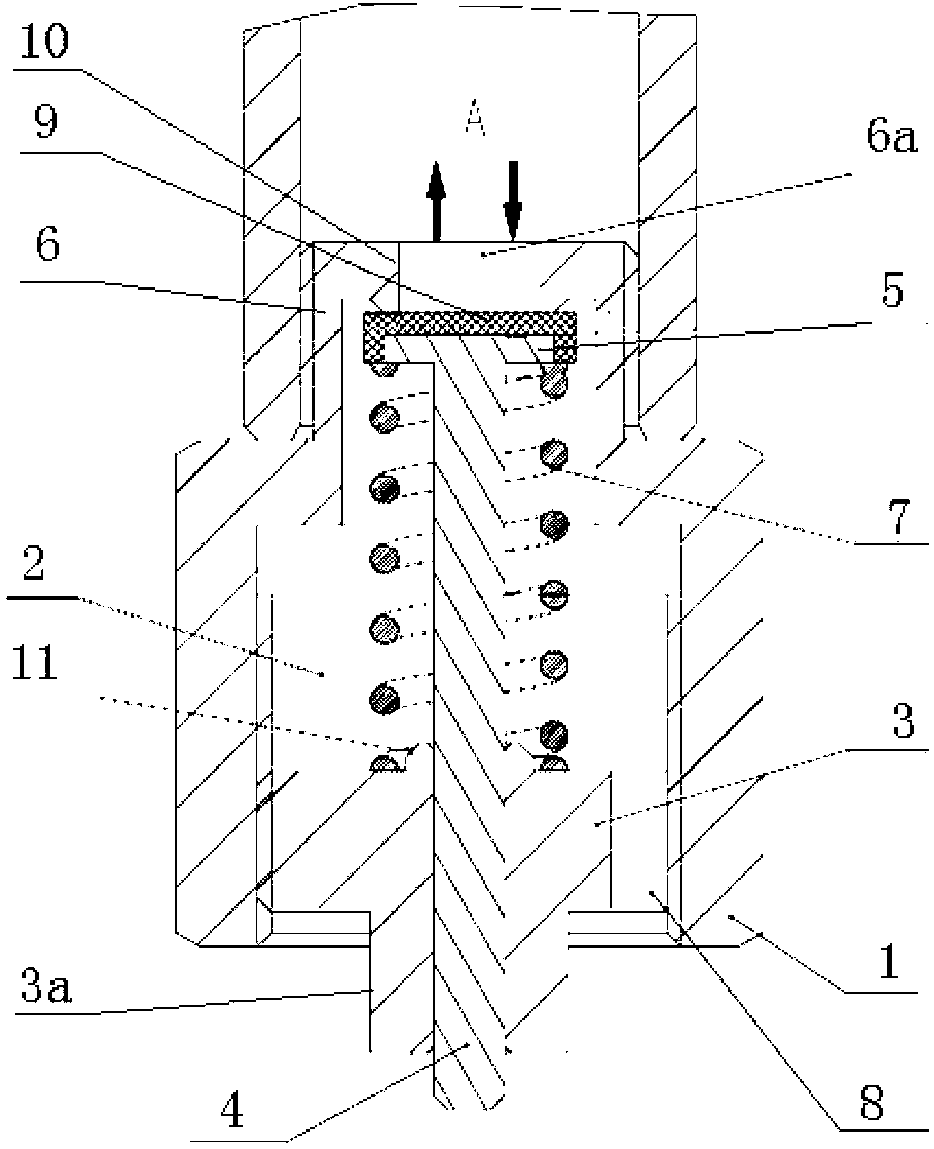
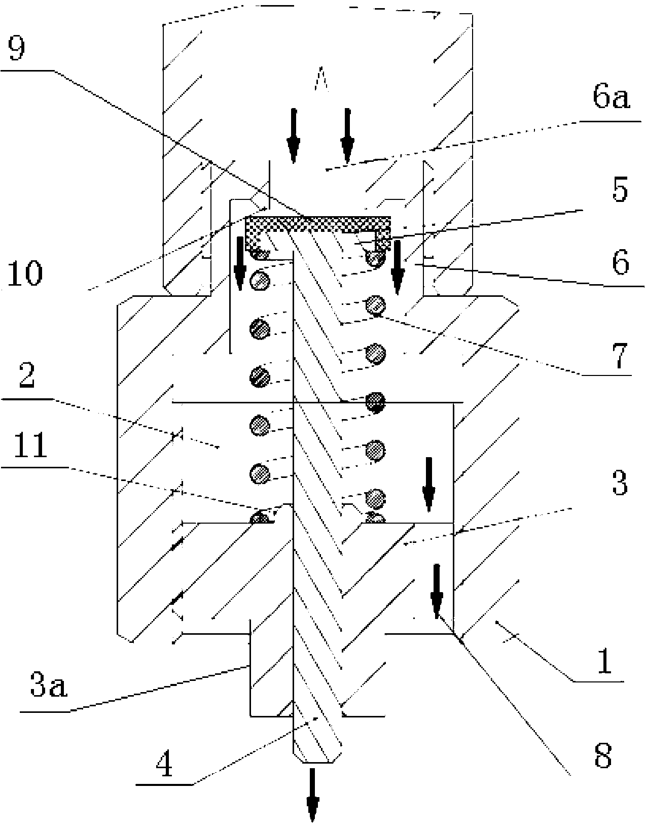
[0014] figure 1 , figure 2 It is a schematic cross-sectional structure diagram of the present invention: the pressure maintaining valve with automatic drainage and sewage discharge function of the present invention includes a valve body 1, a valve cavity 2, a plug 3 at the bottom of the valve body 1, a valve stem 4, and the top of the valve cavity is an inlet connector 6. There is an end seal 10 between the inlet 6a and the wall of the inlet connector 6, and the inlet 6a communicates with the valve cavity 2; the lower end of the valve stem 4 passes through the guide hole in the center of the plug 3, and the upper end of the valve stem 4 is a sealing disc 5 , the sealing disc 5 corresponds to the inlet 6a, the sealing d...


PUM


Abstract

The invention discloses a pressure retaining valve with an automatic water-drain pollution-discharge function. The pressure retaining valve comprises a valve body, a valve chamber, a plug at the bottom end of the valve body, and a valve rod, wherein an inlet connection head is arranged at the top end of the valve chamber, an end seal is arranged between an inlet and the inlet connection head, and the inlet is communicated with the valve chamber; the lower end of the valve rod penetrates through a guide hole in the center of the plug, and a seal disc is arranged at the upper end of the valve rod and corresponds to the inlet; the seal disc is larger than the inlet and is smaller than the inner diameter of the inlet connection head and plays a role of opening and closing the inlet, and a pressure spring is sheathed on the valve rod between the seal disc and the plug; and a discharge port through which the valve chamber is communicated with the outside is formed in the plug. A connection thread is arranged on the outer side of the inlet connection head, and the valve rod is a rubber-vulcanized rod. A rubber sealing layer is arranged on the sealing surface of the upper end of the seal disc on the upper end of the valve rod, and the plug is in threaded connection with the valve body. A hexagonal adjustable head is arranged at the lower end of the plug. The pressure retaining valve can effectively replace the functions of original water drain valves and unloading valves, can realize automatic water drain and pollution discharge of energy storage devices, and reduces the damage effect of hot and humid air sources on the whole system.

Description

technical field [0001] The invention relates to a pressure maintaining valve with the function of automatic drainage and sewage discharge, which belongs to the parts of the automobile air pressure braking system. Background technique [0002] The unloading valve is a valve body assembly that controls the working air pressure of the whole vehicle. The high-temperature and high-pressure gas from the air compressor first enters the unloading valve; the water discharge valve is a valve body assembly installed on the energy storage device. The operation discharges the cooled oil in the energy storage device into the atmosphere. At present, in the design of the whole vehicle system, the common layout matching mode of the two is that the high-temperature and high-pressure gas enters the unloading valve through the pipeline, and then enters the energy storage device through the pipeline. The bottom of the energy storage device is equipped with a water discharge valve; by adjusting t...

Claims


Application Information

Patent Timeline
Patent Type & Authority Applications(China)
IPC IPC(8): F16K17/06
Inventor 陶叶江龚洪李裕峰丁治海聂晓文赵久游
Owner DONGFENG AUTOMOBILE COMPANY
Why Eureka
Try Eureka