
LED (Light Emitting Diode) warning lamp

An LED warning light, one-sided technology, applied in the field of LED lighting, can solve the problems of increased cost of warning light manufacturing, difficult applicability of the reflector, and insufficient uniformity of light output, so as to achieve a simple and clear production process, convenient assembly, and light efficiency utilization. high effect

Active Publication Date: 2013-04-03
GUANGZHOU FORDA SIGNAL
View PDF9 Cites 3 Cited by
  • Summary
  • Abstract
  • Description
  • Claims
  • Application Information

AI Technical Summary

Problems solved by technology

In addition, the warning lights that use reflective bowls to mix light are not uniform enough and the light effect is poor; for warning lights of different sizes, the reflective bowls are difficult to achieve applicability, and different warning lights require different reflective bowls , thus adding cost to the manufacture of warning lights

Method used


Image

  • LED (Light Emitting Diode) warning lamp
  • LED (Light Emitting Diode) warning lamp
  • LED (Light Emitting Diode) warning lamp

Examples


Embodiment 1

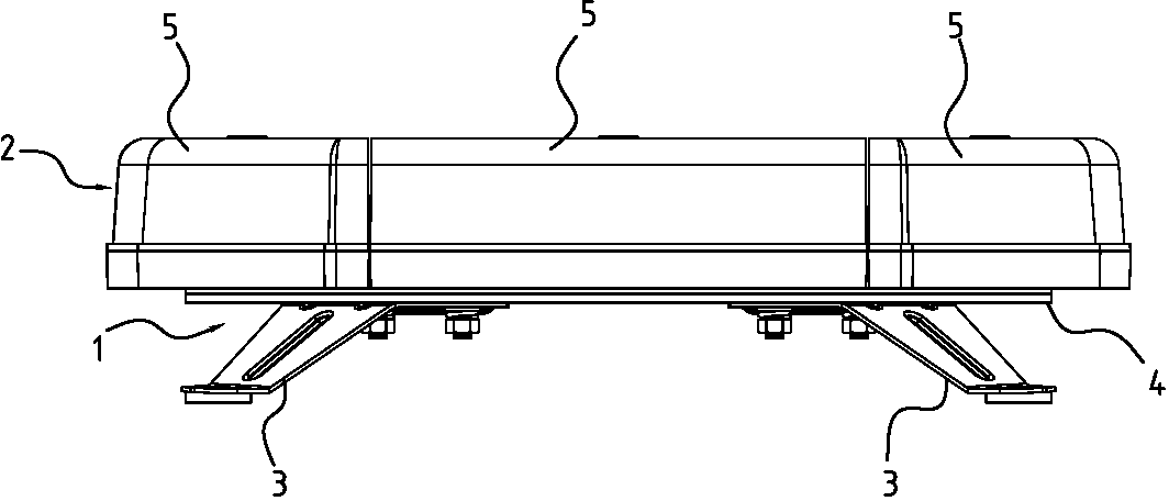
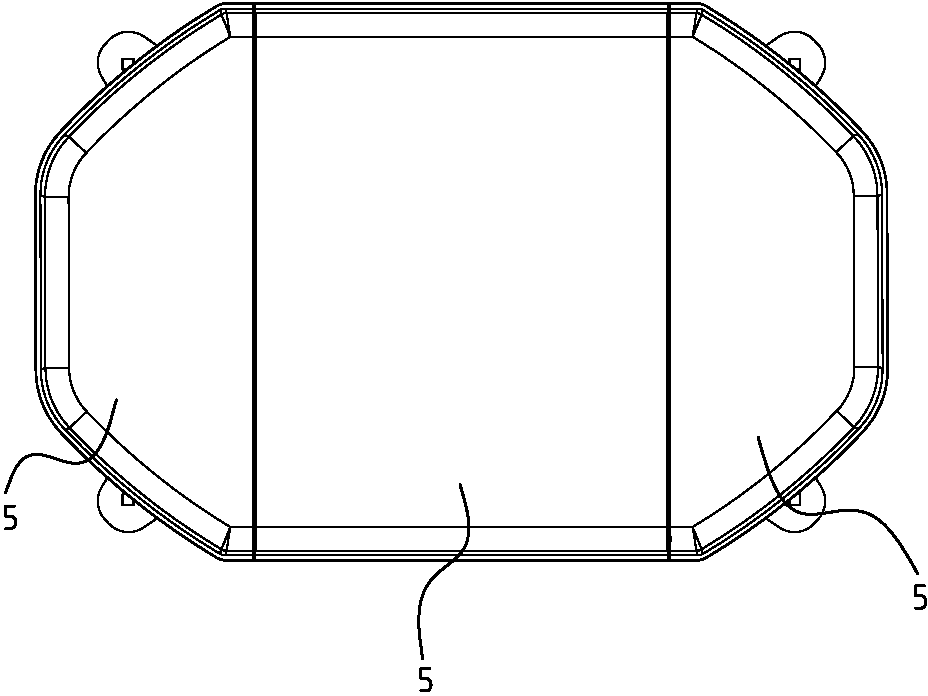
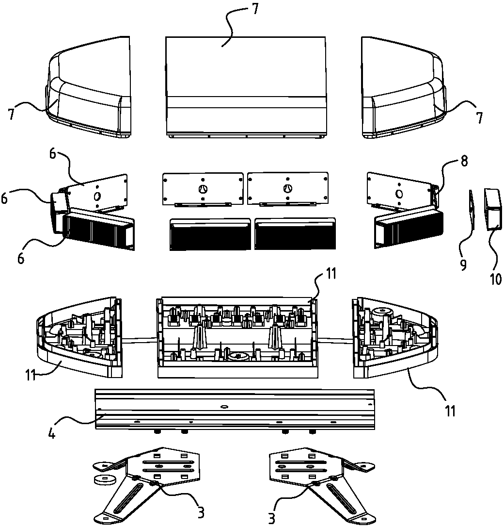
[0019] Such as Figures 1 to 3 As shown, an LED warning light includes a base 1 and a light-emitting assembly 2 arranged on the base 1 . The light-emitting assembly 2 is composed of three light-emitting units 5 , which are the middle light-emitting unit 5 and the end light-emitting units 5 located on both sides of the middle light-emitting unit 5 . The adjacent light-emitting units 5 are connected in series by plugging, so that the electrical connection between the light-emitting units 5 is more convenient. The light-emitting unit 5 includes an optical module 6, a lamp holder 11 and a mask 7 matched with the lamp holder 11, the optical module 6 is fixed on the lamp holder 11 by a fixing bracket 8, and the light emitting of the optical module 6 face outward. Such as image 3 As shown, the base 1 includes a strip-shaped connecting bracket 4 and mounting frames 3 located at both ends of the bottom of the connecting frame 4; the mounting frame 3 is used to support the entire wa...

Embodiment 2

[0022] The difference from that described in Example 1 is that the radius of curvature of the arc-shaped protrusion 21 shown is 0.2-2.0mm; the angle θ1 between one side of the first triangular protrusion 17 and the horizontal line is 36°, and the other side is between the horizontal line and the horizontal line. The angle θ2 is 5.7°; the included angle θ3 between one side of the second triangular protrusion 18 and the horizontal line is 35°, and the included angle θ4 between the other side and the horizontal line is 4°; the included angle θ5 between one side of the third triangular protrusion 19 and the horizontal line The included angle θ6 between the other side and the horizontal line is 4.75°; the included angle θ7 between one side of the fourth triangular protrusion 20 and the horizontal line is 30°, and the included angle θ8 between the other side and the horizontal line is 6.85°.

Embodiment 3

[0024] The radius of curvature of the arc-shaped protrusion 21 shown is 0.2~2.0mm; the angle θ1 between one side of the first triangular protrusion 17 and the horizontal line is 30°, and the angle θ2 between the other side and the horizontal line is 3°; the second triangular protrusion 17 The included angle θ3 between one side of the raised 18 and the horizontal line is 28°, the included angle θ4 between the other side and the horizontal line is 2°; The angle θ6 is 4°; the angle θ7 between one side of the fourth triangular protrusion 20 and the horizontal line is 25°, and the angle θ8 between the other side and the horizontal line is 5°.


PUM


Abstract

The invention relates to an LED (Light Emitting Diode) warning lamp which comprises a base and a light emitting assembly arranged on the base. The light emitting assembly consists of more than two light emitting units. The base comprises a connecting bracket and an installation frame arranged at the bottom of the connecting bracket. The light emitting units are arranged on the connecting bracket and adjacent light emitting units are connected in series. Each light emitting unit comprises an installation base and more than one optical module arranged on the installation base. The optical modules of all light emitting units are arranged to form a 360-degree light source. The warning lamp provided by the invention distributes light in form of a lens, and refracts light to different angular areas according to light distribution requirements, so that the optical efficiency utilization rate is high. A light distributing face is arranged in the circumference at 360 degrees, so that laws and regulations of ECER65T warning lamps can be met. With the adoption of the form of lens and unit assembly, the lamp is convenient to assemble, the manufacturing process is simple and clear, and the production cost is lowered.

Description

technical field [0001] The invention relates to the field of LED lighting, in particular to an LED warning light. Background technique [0002] Existing LED warning lights generally include a lamp holder, an LED light source and a reflective bowl, and the LED light source reflects light through the reflective bowl to play a warning role. In the entire warning light, the warning effect is mainly produced by the reflective bowl, so the quality of the reflective bowl directly affects the warning effect of the warning light. Although the reflective bowls of existing warning lights have different structures, many of them fail to meet the requirements of relevant laws and regulations. For example, a kind of LED warning light whose Chinese patent publication number is CN202349830 includes a base, and a circuit board is arranged on the base, and a reflective cup is arranged on the circuit board, and the periphery of the reflective cup is an outward arc surface. LED lamp beads are ...

Claims


Application Information

Patent Timeline
Patent Type & Authority Applications(China)
IPC IPC(8): F21S8/00F21V5/04F21V19/00F21Y101/02F21Y115/10
Inventor 刘信国
Owner GUANGZHOU FORDA SIGNAL
Learn More