Orientation reference mirror

A reference mirror and azimuth technology, applied in the direction of instruments, installations, measuring devices, etc., can solve the problems of inconvenient azimuth adjustment and difficulty in erecting auto-collimating theodolite, so as to improve efficiency, make azimuth and level adjustment simple and fast, and ensure accuracy and the effect of precision

Active Publication Date: 2013-04-03
TIANJIN NAVIGATION INSTR RES INST
View PDF5 Cites 5 Cited by
  • Summary
  • Abstract
  • Description
  • Claims
  • Application Information

AI Technical Summary

Problems solved by technology

The existing ordinary optical azimuth reference mirror has defects such as difficulty in erecting the self-collimating theodolite and inconvenient azimuth adjustment during the installation process

Method used


Image

  • Orientation reference mirror
  • Orientation reference mirror
  • Orientation reference mirror

Examples


Embodiment Construction

[0020] The embodiments of the present invention will be described in detail below in conjunction with the accompanying drawings; it should be noted that the embodiments are illustrative, not restrictive, and cannot limit the protection scope of the present invention.

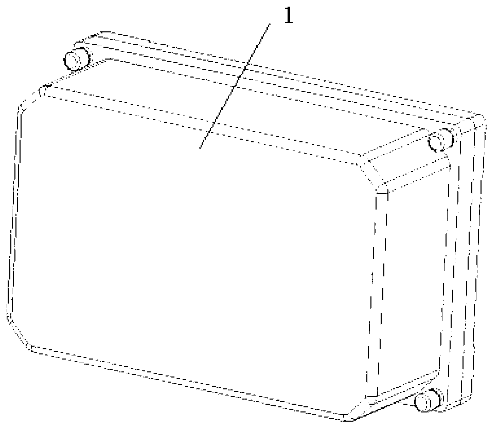
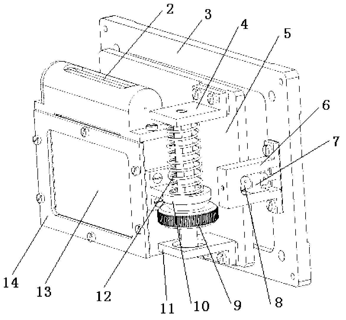
[0021] A kind of azimuth reference mirror, comprises optical reflection mirror and optical azimuth reference mirror installation base 3, and this optical reflection mirror is high-precision roof prism 13, and this high-precision roof prism is installed in the roof prism installation base 14, and this roof prism is installed A horizontal datum blister 2 is installed on the upper surface of the base.

[0022] A mounting plate 5 is arranged between the mounting base of the roof prism and the mounting base of the optical azimuth reference mirror. One end of the mounting plate is hinged on the installation base of the optical azimuth reference mirror, and the other end is installed on the installation base of the opt...


PUM


Abstract

The invention relates to an orientation reference mirror which comprises an optical reflection mirror and an optical orientation reference mirror mounting base; the optical reflection mirror is a high-accuracy ridge prism which is installed in a ridge prism mounting base; the upper surface of the ridge prism mounting base is provided with a horizontal reference blister; a cylindrical structure at the rear part of the ridge prism mounting base is installed in a round hole of a mounting plate; a horizontal leveling mechanism on the mounting plate is installed at one side of the ridge prism mounting base; and one end of the mounting plate is articulated on an optical orientation reference mirror mounting base, and the other end of the mounting plate is installed on the optical orientation reference mirror mounting base through an orientation regulating mechanism. The orientation reference mirror provided by the invention is the orientation reference mirror based on the ridge prism, which is reasonable in design, is flexible to operate, and is simple and rapid in orientation and horizontal regulation; and by utilizing the orientation reference mirror, the erection difficulty of an auto-collimation theodolite can be lowered, the efficiency can be improved, and the accurate equipment mounting orientation can be ensured.

Description

technical field [0001] The invention relates to the field of optical devices, in particular to an azimuth reference mirror based on a roof prism. Background technique [0002] The optical azimuth reference mirror refers to a high-precision optical device that uses the normal of the optical mirror to represent a specific azimuth edge. The optical azimuth reference mirror is mainly used in the production, test and verification places of inertial equipment, and at the same time, it is installed at the position that needs to represent the azimuth reference of the carrier. The optical azimuth reference mirror is mainly composed of an optical reflector and an installation base. The optical mirror provides high-precision optical reflection normal, and the installation base provides the installation reference for the optical mirror and ensures that the optical azimuth reference mirror can be stably installed on other equipment or bases. The existing ordinary optical azimuth refere...

Claims


Application Information

Patent Timeline
Patent Type & Authority Applications(China)
IPC IPC(8): G01C25/00G01C1/02G02B7/18
Inventor 徐凯刘昱张群刘畅王鑫张缨皮寿熹
Owner TIANJIN NAVIGATION INSTR RES INST
Why Eureka
Try Eureka