Transfer device for erecting electric power tower

A technology for power poles and towers and transfer devices, which is applied in the direction of freight vehicles, transportation and packaging, and transport objects. It can solve the problems of low efficiency and laborious erection of power poles and towers, so as to improve erection efficiency, reduce erection difficulty, and save manpower. Effect

Pending Publication Date: 2022-01-21
国网河南省电力公司镇平县供电公司
View PDF13 Cites 0 Cited by
  • Summary
  • Abstract
  • Description
  • Claims
  • Application Information

AI Technical Summary

Problems solved by technology

But this invention can not solve the problem of laborious and low efficiency when erecting electric pole tower

Method used


Image

  • Transfer device for erecting electric power tower
  • Transfer device for erecting electric power tower
  • Transfer device for erecting electric power tower

Examples


Embodiment 1

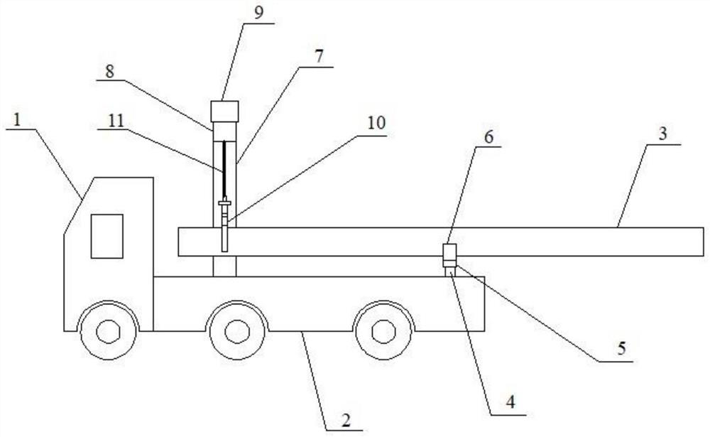
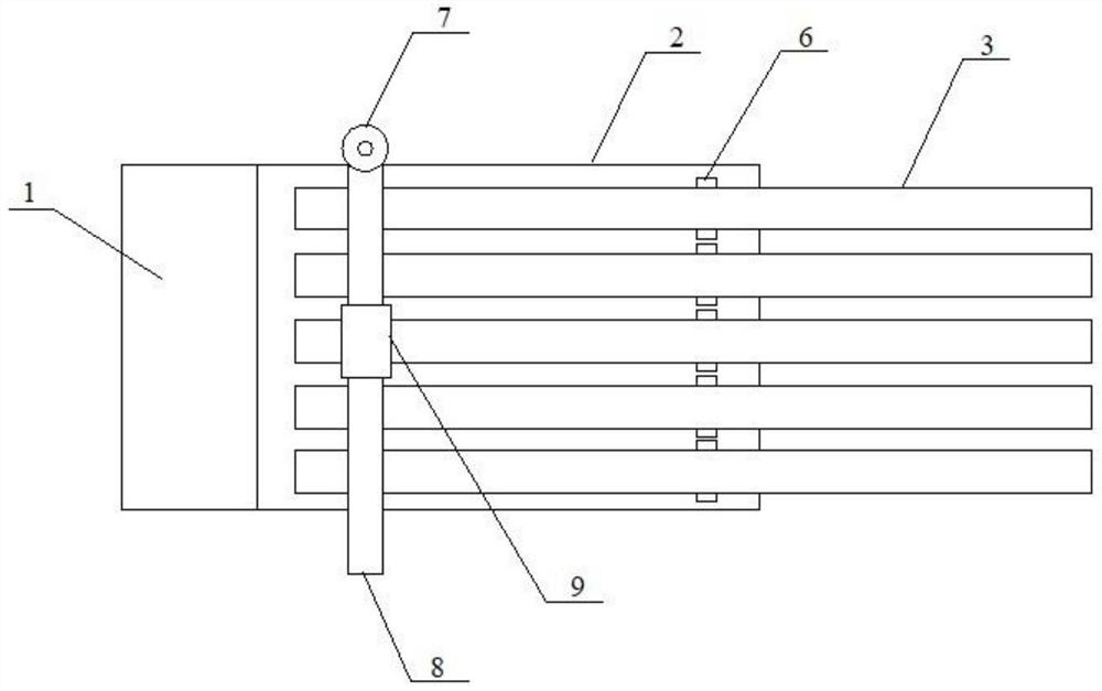
[0028] like Figure 1~3 As shown, a transfer device for the erection of power poles and towers includes a tractor 1 and a flat frame 2, and the flat frame 2 is provided with a plurality of support mechanisms for carrying power poles and towers 3, and one for lifting power The lifting mechanism at the end of the pole tower 3, the support mechanism is supported in the middle of the power pole tower 3 near the upper end, after the support mechanism lifts the upper part of the power pole tower 3 to a certain height, the lifting mechanism grabs the lower part of the power pole tower 3, And the power pole tower is rotated 3 to the outside of the flat vehicle frame 2, and then the power pole tower is lowered into the foundation pit.

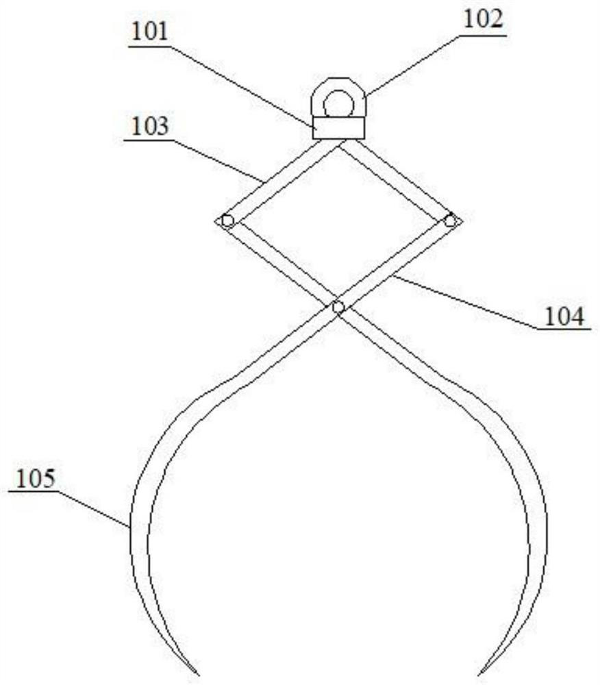
[0029] The support mechanism includes a lifting part 4, a connecting block 5 and an arc support seat 6, the lifting part 4 is fixedly arranged on the flatbed frame 2, the connecting block 5 is arranged on the upper end of the lifting part 4, the The ar...

Embodiment 2

[0035] like Figure 4 As shown, the embodiment of the present invention is used for the transfer device for the erection of power poles and towers. As a further improvement of Embodiment 1, it differs from Embodiment 1 in that:

[0036] The arc-shaped support base includes a first arc-shaped support rod 61 and a second arc-shaped support rod 62 whose two ends are respectively hinged to each other, and the first arc-shaped support rod 61 is located inside the second arc-shaped support rod 62 , A shaft body 63 is arranged on the lower part of the second arc-shaped support rod 62 , and a bearing 64 is arranged on the connecting block 5 , and the shaft body 63 is connected with the bearing 64 .

[0037] The lifting part 4 is an electric push rod.

Embodiment 3

[0039] like Figure 5 As shown, the embodiment of the present invention is used for the transfer device for the erection of power poles and towers. As a further improvement of Embodiment 1, it differs from Embodiment 1 in that:

[0040] Described rotating horizontal arm comprises rotating disk 81, motor 82 and two crossbars 83, and described rotating disk 81 is arranged on the upper end of described vertical bar 7, and planetary gear is arranged inside described rotating disk 81, and described planetary gear and described motor 82 The main shaft is connected to the transmission, and the two crossbars 83 are arranged in parallel on one side of the turntable 81, and the two crossbars 83 are provided with strip-shaped through holes 84.

[0041] The lifting component is a winch.


PUM


Abstract

The invention discloses a transfer device for erecting an electric power tower, and belongs to the technical field of electric power tower transportation equipment. The transfer device comprises a tractor and a flat car frame, and the flat car frame is provided with a plurality of supporting mechanisms used for bearing the electric power tower and a lifting mechanism used for lifting the end of the electric power tower; the supporting mechanism is supported at the position, close to the upper end, of the middle of the electric power tower, after the supporting mechanism supports and lifts the upper portion of the electric power tower to a certain height, the lifting mechanism grabs the lower portion of the electric power tower and rotates the electric power tower to the outer side of the flat car frame, and then the electric power tower is lowered into a foundation pit. The electric power tower can be erected by means of the transfer trolley, so that manpower is reduced, and the electric power tower erecting efficiency is improved.

Description

technical field [0001] The invention relates to the technical field of power pole and tower transportation equipment, in particular to a transfer device for erecting power poles and towers. Background technique [0002] In mountainous areas, rural areas and other areas, cement towers are still common transmission line infrastructure. When erecting cement poles and towers, vehicles are usually used to transport multiple cement poles to the route to be erected, and they are removed one by one and placed near the foundation pit along the line. Landfill erection usually requires a lot of manpower, and the erection efficiency is low. As labor costs continue to rise, a mechanical auxiliary tool that can reduce the difficulty of cement pole erection is needed. [0003] The patent document with the notification number CN 112498440 A discloses a power tower transfer device, which relates to the technical field of power equipment transfer. It includes a front car body and a rear car...

Claims


Application Information

Patent Timeline
Patent Type & Authority Applications(China)
IPC IPC(8): B60P1/54B60P7/12
CPCB60P1/5423B60P7/12
Inventor 吴立勇鲁萍吴阳刘栋丁熙安冯戈闵晓庞子欣
Owner 国网河南省电力公司镇平县供电公司
Why Eureka
Try Eureka