
Wafer testing device

A technology for wafer testing and carrying wafers, which is applied in the direction of measuring devices, measuring device casings, measuring electronics, etc., and can solve problems such as uneven force, non-conforming depth of pin points, deformation, etc.

Inactive Publication Date: 2013-04-03
SHENZHEN TITAN MICRO ELECTRONICS
View PDF6 Cites 2 Cited by
  • Summary
  • Abstract
  • Description
  • Claims
  • Application Information

AI Technical Summary

Problems solved by technology

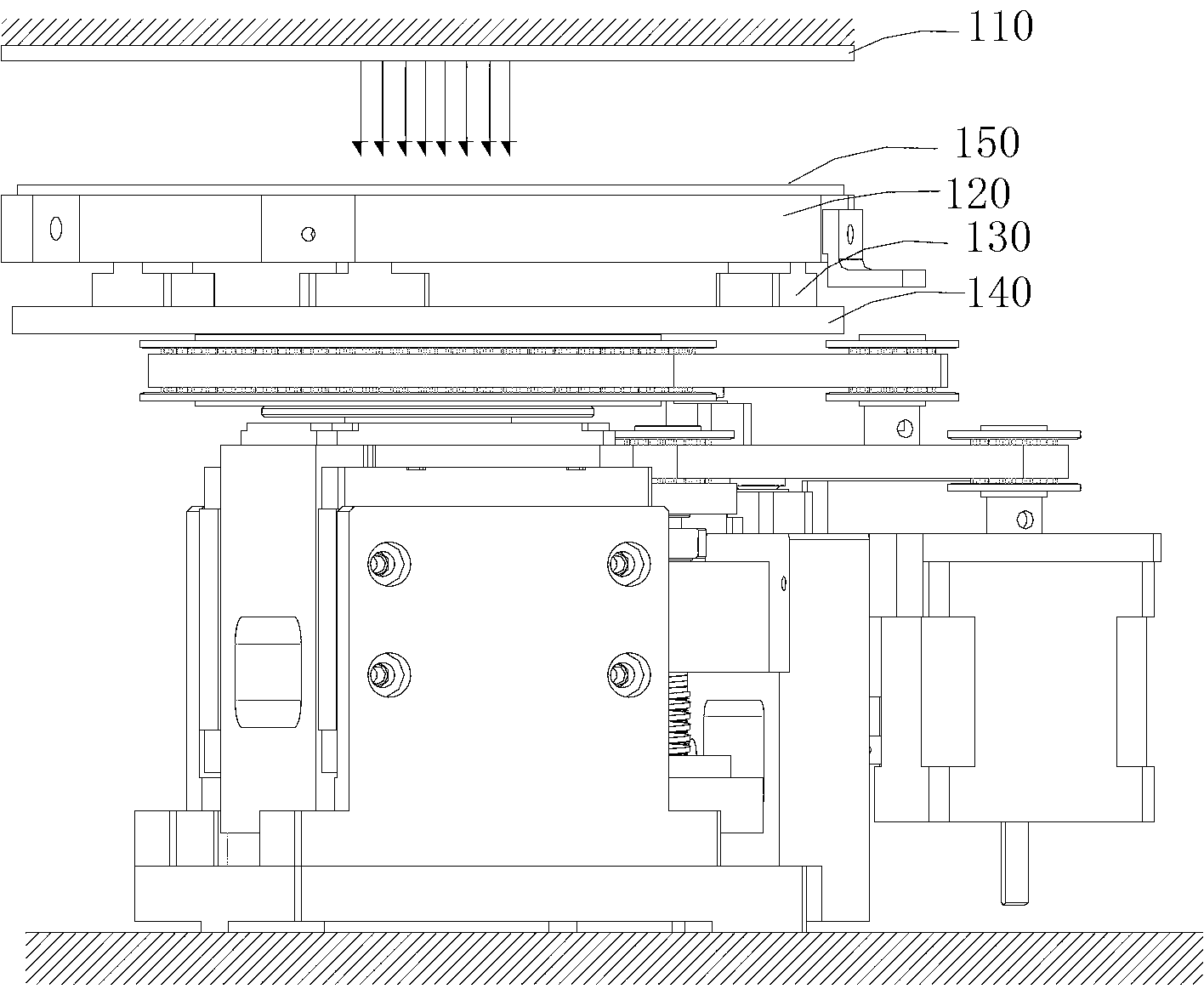
Due to reasons such as uneven force, easy deformation of plastic materials, and insufficient strength, any one of the three wafer holder holders 130 is deformed, and the wafer holder 120 will be deformed.
This leads to the problem that the depth of the needle point does not meet the requirements when the probe contacts the wafer 150
Thereby affecting the accuracy of the test and the service life of the pin card 110

Method used


Image

  • Wafer testing device
  • Wafer testing device

Examples


Embodiment Construction

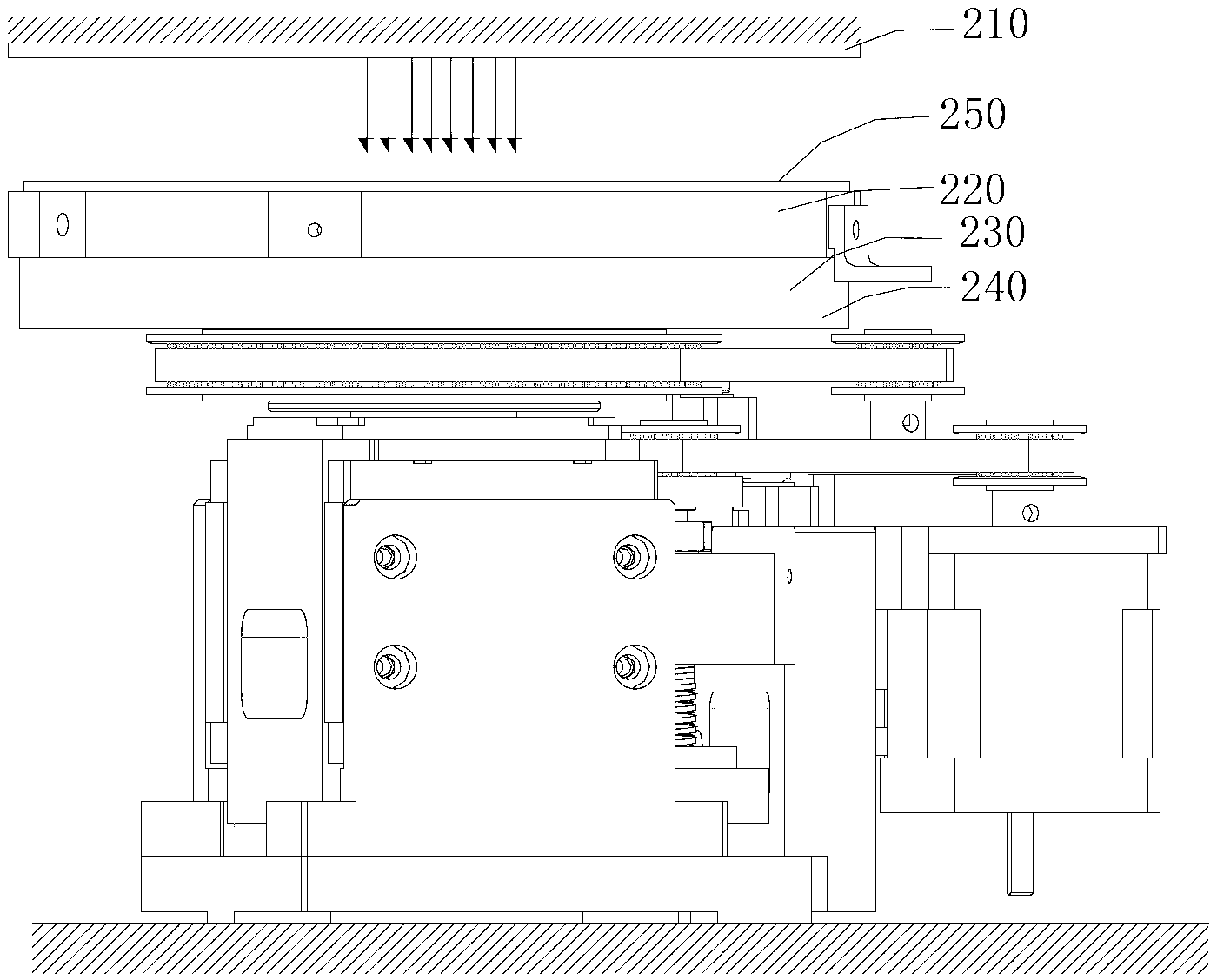
[0014] Please refer to figure 2 , an embodiment provides a wafer testing device. The wafer testing device includes a pin card 210 with a probe, a wafer stage 220 for carrying a wafer, a wafer stage fixing plate 230 for fixing the wafer stage 220, a fixing plate mounting plate 240 for fixing the wafer stage fixing plate 230, and A moving mechanism that drives the fixed plate mounting plate 240 to move. The wafer stage fixing plate 230 is an electrically insulating plate. The moving mechanism can drive the wafer stage 220 to move along the X, Y, and Z axes, so that the probes on the needle card 210 can contact the wafer 150 to test the wafer 150 .

[0015] The wafer testing device uses the wafer stage fixing plate 230 instead of the commonly used way of using three wafer stage fixing seats to support the wafer stage. Since the wafer stage fixing plate 230 is an electrically insulating plate, the stress on it will be relatively uniform. In this way, the wafer carrier 220 is ...


PUM


Abstract

The invention provides a wafer testing device. The device comprises a probe card with probes, a bearing platform for bearing a wafer, a bearing platform fixing plate for fixing the bearing platform, a fixing plate mounting plate for fixing the bearing platform fixing plate and a moving mechanism for driving the fixing plate mounting plate to move. The bearing platform fixing plate is electrically insulated. According to the wafer testing device, the bearing platform fixing plate is used for replacing a common mode in which three bearing platform fixing seats are used for bearing a bearing platform, and as the bearing platform fixing plate is electrically insulated, the stress is uniform. Accordingly, the bearing platform cannot be deformed, and the wafer testing device has the advantages that the test is accurate, and the probe card service life is long.

Description

technical field [0001] The invention relates to a semiconductor testing device, in particular to a wafer testing device. Background technique [0002] In the field of semiconductor manufacturing, wafer testing equipment is generally used in the chip manufacturing process. like figure 1 As shown, a commonly used wafer testing device includes a needle card 110, a wafer stage 120, a wafer stage fixing base 130, a fixing base mounting plate 140 and a moving mechanism. The needle card 110 is arranged on the top of the wafer holder 120, the wafer holder 120 is fixed on the holder 130 of the wafer holder, the holder 130 of the wafer holder is fixed on the installation plate 140 of the holder, and the installation plate 140 of the holder is fixed on the moving mechanism superior. The moving mechanism can drive the mounting plate 140 of the fixed seat to move along the X, Y, and Z axes, thereby adjusting the position of the wafer stage 120 . [0003] The wafer stage 120 is one of...

Claims


Application Information

Patent Timeline
IPC IPC(8): G01R1/04G01R1/067
Inventor 龚虎张伟梁锦昌江耀燕门洪达
Owner SHENZHEN TITAN MICRO ELECTRONICS
Learn More