
Unattended power supply system of sensor

A sensor power supply, electrolyzer technology, applied in the direction of electrical program control, comprehensive factory control, etc., can solve the problems of accelerating battery aging, increasing workload and complexity, and high battery price, so as to reduce human activities and improve reliability and stability effects

Inactive Publication Date: 2013-04-03
STATE GRID CORP OF CHINA +1
View PDF0 Cites 3 Cited by
  • Summary
  • Abstract
  • Description
  • Claims
  • Application Information

AI Technical Summary

Problems solved by technology

[0002] With the development of power automation and informatization, remote monitoring of power systems has become more and more important. Because power transmission has large areas, wide distribution, large network spans, and many places with steep terrain, it even has to go through many unmanned In modern technology, the monitoring of these systems often relies on sensors to transmit information remotely. A stable power supply system is the prerequisite for reliable operation of sensors. Power transmission is often high-voltage power, which cannot be directly used to provide working power for sensors. In the past, people The various power storage devices developed such as batteries can only provide power to the system within a certain period of time. The combined system of photovoltaic power generation modules and batteries can realize self-supply of electricity, but on the one hand, the price of batteries is too high, on the other hand, due to the geographical location of the power system A large part of the environment is relatively harsh, which not only increases the aging speed of the battery, but also causes great uncertainty to the system. The combination of photovoltaics and fuel cells provides another option, but this system often requires human resources. Regular observation and artificial water addition increase the workload and tediousness

Method used


Image

  • Unattended power supply system of sensor

Examples


Embodiment Construction

[0007] In order to more fully explain the implementation of the present invention, the implementation examples of the present invention are provided. These implementation examples are only elaborations of the present invention and do not limit the scope of the present invention. Select the corresponding preparation to meet the water requirements for electrolytic hydrogen production.

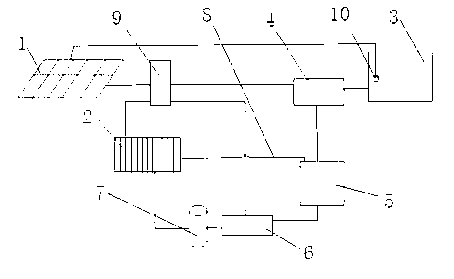
[0008] as attached figure 1 As shown, the unattended sensor power supply system includes a solar photovoltaic power generation module 1 and a fuel cell stack 2, and a water storage and sedimentation tank 3 is set in the system, and a water purification device 4 is set behind the water storage and sedimentation tank, and the water enters after purification Pure water tank 5, electrolytic cell 6, water for electrolytic hydrogen production comes from pure water tank 5, hydrogen storage tank 7 for the fuel cell stack 2 is arranged behind the electrolytic cell 6, and a discharge water recovery pipe 8 ...


PUM


Abstract

The invention relates to an unattended power supply system of a sensor, and belongs to the power field of an independent power supply. The system comprises a solar photovoltaic power generation assembly and a fuel cell stack. A water storage settling pond is arranged in the system, and a water purifying device is arranged behind the water storage settling pond. Purified water enters a purified water tank, and water for electrolytic hydrogen making by an electrolytic cell is from the purified water tank. A hydrogen storage tank for operation of the fuel cell stack is arranged behind the electrolytic cell, and an outlet water recovery pipe is arranged on the fuel cell stack and connected to the purified water tank. The system is provided with a controller for centralized control of the solar photovoltaic power generation assembly, the fuel cell stack, the water purifying device and the electrolytic cell. The system provided with corresponding detecting and automatic controller devices can completely realize automation, the power generation efficiency of the system is high, and the system can be integrally arranged in remote independent power supply monitoring areas.

Description

technical field [0001] The invention relates to an unattended system, in particular to an unattended sensor power supply system, which belongs to the field of independent electric power supply. Background technique [0002] With the development of power automation and informatization, remote monitoring of power systems has become more and more important. Because power transmission has large areas, wide distribution, large network spans, and many places with steep terrain, it even has to go through many unmanned In modern technology, the monitoring of these systems often relies on sensors to transmit information remotely. A stable power supply system is the prerequisite for reliable operation of sensors. Power transmission is often high-voltage power, which cannot be directly used to provide working power for sensors. In the past, people The various power storage devices developed such as batteries can only provide power to the system within a certain period of time. The comb...

Claims


Application Information

Patent Timeline
Patent Type & Authority Applications(China)
IPC IPC(8): G05B19/418
Inventor 傅强朱建新高远郝文杰郭飞飞
Owner STATE GRID CORP OF CHINA
Learn More