A water flow power generation device using the terrain drop in remote mountainous areas

A technology of hydroelectric power generation and mountain area, applied in the direction of hydroelectric power generation, reaction engine, engine components, etc., can solve the problems of power loss, affecting power generation, inconvenient to build power stations, etc.

Active Publication Date: 2021-06-25
芜湖贝斯特新能源电力设计研究院有限公司
View PDF7 Cites 0 Cited by
  • Summary
  • Abstract
  • Description
  • Claims
  • Application Information

AI Technical Summary

Problems solved by technology

[0002] "Electricity" has become one of the indispensable energy sources in our lives. After more than a hundred years of development, it has basically been popularized. However, in some remote mountainous areas, the population is scattered and the terrain is undulating. Long-distance transmission, because the distance is too far, a lot of power will be lost in the process, which will increase the cost of electricity
[0003] Since ancient times, our country has the habit of living by the water. There are rivers in places where there are people, so the following small hydroelectric power stations have been built on the riverside. Rotating leaves are installed in the river, and the rotating leaves are driven by the water flow to generate electricity. Because the river water is evenly impacted On the rotating blade, the impact force on the left and right sides of the rotating blade is almost the same, and the power is lost. If the wind or garbage affects the direction of the water flow, it will affect the rotation direction of the power generation device, change the electrode, and affect the power generation. We propose a water flow power generation device using terrain drop in remote mountainous areas to solve the problem

Method used


Image

  • A water flow power generation device using the terrain drop in remote mountainous areas
  • A water flow power generation device using the terrain drop in remote mountainous areas
  • A water flow power generation device using the terrain drop in remote mountainous areas

Examples


Embodiment Construction

[0030] The following will clearly and completely describe the technical solutions in the embodiments of the present invention with reference to the accompanying drawings in the embodiments of the present invention. Obviously, the described embodiments are only some, not all, embodiments of the present invention. Based on the embodiments of the present invention, all other embodiments obtained by persons of ordinary skill in the art without making creative efforts belong to the protection scope of the present invention.

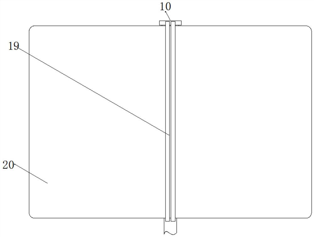
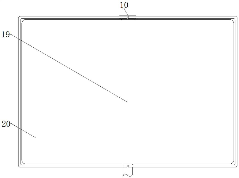
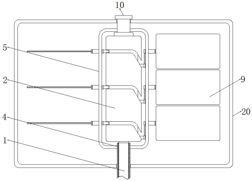
[0031] see Figure 1-12 , a water flow power generation device utilizing terrain drop in remote mountainous areas, comprising a support shaft 1, a control wheel 2 is fixedly connected to the outside of the support shaft 1, and an adjustment groove 3 is opened on the outside of the control wheel 2, and the adjustment groove 3 is annular.

[0032] The outer side of the support shaft 1 and the upper and lower sides of the control wheel 2 are fixedly connected wit...


PUM


Abstract

The invention discloses a hydroelectric power generation device utilizing terrain drop in remote mountainous areas, and a hydroelectric generating device utilizing terrain drop in remote mountainous areas, comprising a support shaft, a control wheel is fixedly connected to the outer side of the support shaft, and the outer An adjustment slot is provided, and an outer cover is fixedly connected to the outer side of the support shaft and above and below the control wheel. This far-mountainous area uses a hydroelectric power generation device with a terrain drop. By opening an adjustment groove on the outside of the control wheel, the water flow passes through the baffle net to impact the vertical force plate on the right side, and the force plate is affected by the adjustment groove when rotating. Keep flipping, as shown in Figure 3-4, when the force plate rotates, the thrust of the water flow received by the force plate in the vertical state on the right side is much greater than the thrust received by the force plate in the horizontal state on the left side, which reduces the loss of power , the rotation direction of the fixed frame is guaranteed to be consistent, the power generation efficiency is improved, and the power conversion cost is saved.

Description

technical field [0001] The invention relates to the technical field of hydroelectric power generation, in particular to a water flow power generation device utilizing terrain drop in remote mountainous areas. Background technique [0002] "Electricity" has become one of the indispensable energy sources in our lives. After more than a hundred years of development, it has basically been popularized. However, in some remote mountainous areas, the population is scattered and the terrain is undulating. Long-distance transmission, because the distance is too long, will consume a lot of power in the process, increasing the cost of electricity. [0003] Since ancient times, our country has the habit of living by the water. There are rivers in places where there are people, so the following small hydroelectric power stations have been built on the riverside. Rotating leaves are installed in the river, and the rotating leaves are driven by the water flow to generate electricity. Becau...

Claims


Application Information

Patent Timeline
Patent Type & Authority Patents(China)
IPC IPC(8): F03B13/00F03B3/14F03B11/08
CPCF03B3/14F03B11/08F03B13/00F05B2220/706Y02E10/20
Inventor 文杰
Owner 芜湖贝斯特新能源电力设计研究院有限公司
Why Eureka
Try Eureka