
Uniform temperature plate structure and manufacturing method thereof

A manufacturing method and technology of a temperature equalizing plate, which can be applied in lighting and heating equipment, electrical components, electric solid devices, etc., and can solve the problems of different heat and different power of electronic components.

Active Publication Date: 2013-04-03
ASIA VITAL COMPONENTS SHENZHEN CO LTD
View PDF5 Cites 8 Cited by
  • Summary
  • Abstract
  • Description
  • Claims
  • Application Information

AI Technical Summary

Problems solved by technology

[0006] Furthermore, the power of each electronic component is different, so the heat generated is also different. When the heat generated by the electronic components is quite different, it is not suitable to use a uniform temperature plate to conduct heat between the two at the same time. Work

Method used


Image

  • Uniform temperature plate structure and manufacturing method thereof
  • Uniform temperature plate structure and manufacturing method thereof
  • Uniform temperature plate structure and manufacturing method thereof

Examples


Embodiment Construction

[0045] The above-mentioned purpose of the present invention and its structural and functional characteristics will be described based on the preferred embodiments of the accompanying drawings.

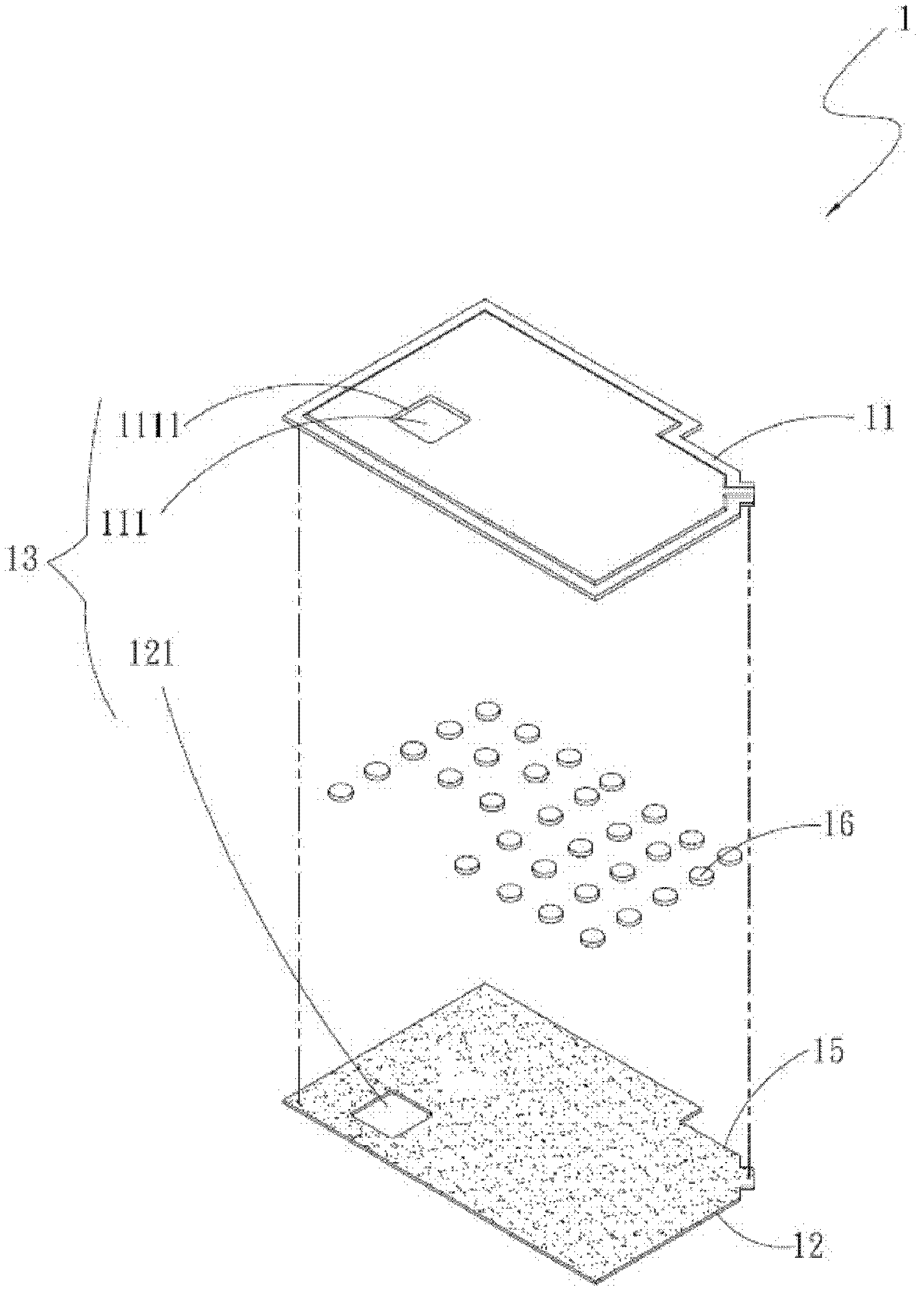
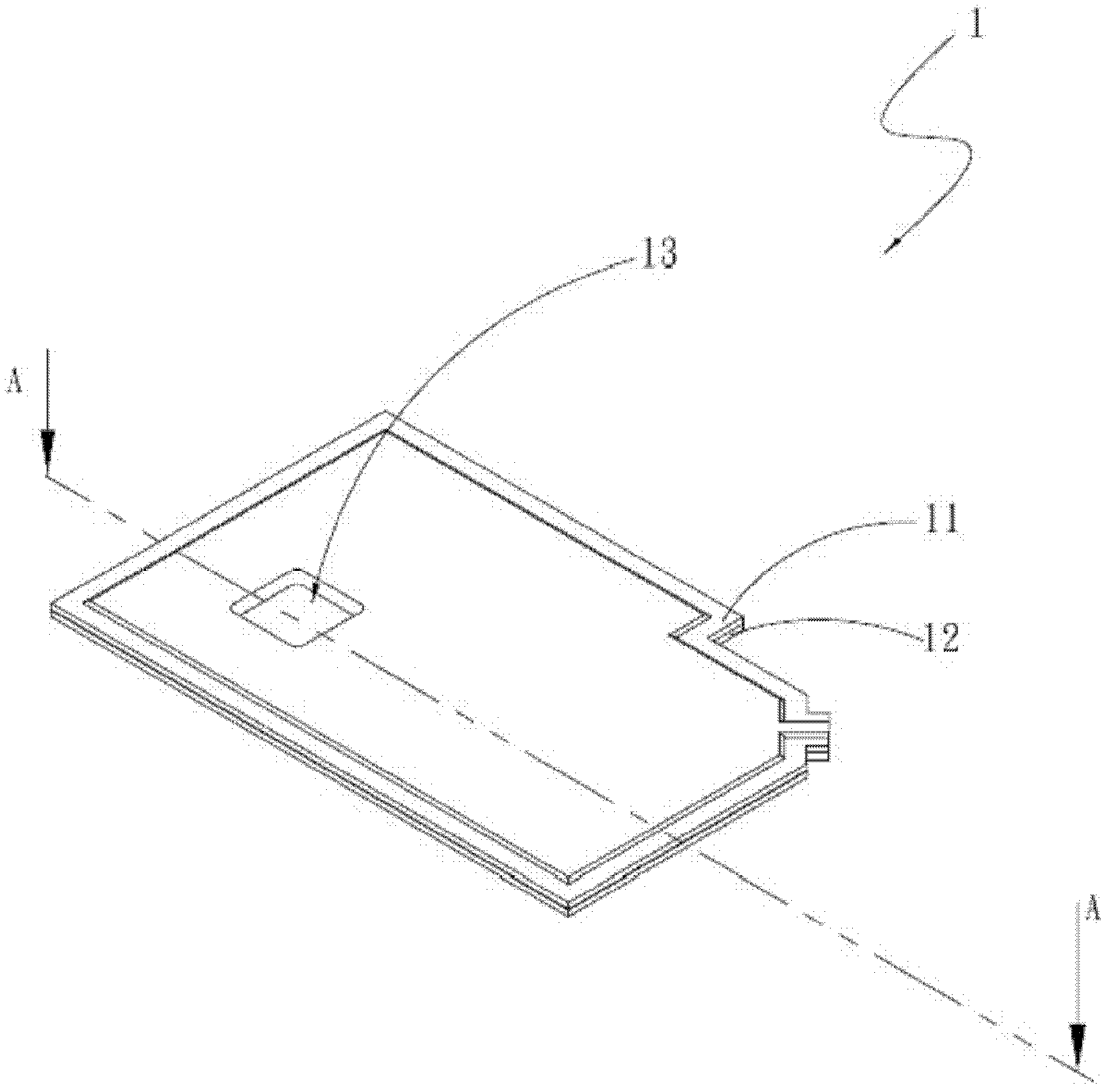
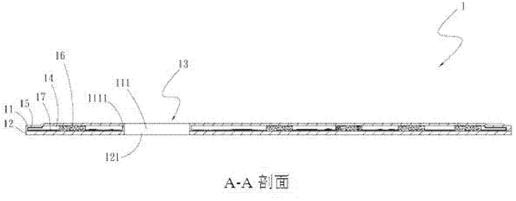
[0046] see figure 1 , figure 2 , image 3 , is the three-dimensional decomposition and assembly and the A-A sectional view of the first embodiment of the chamber structure of the present invention. The chamber structure includes: a body 1;

[0047] The main body 1 has a first plate body 11 and a second plate body 12, the first and second plate bodies 11, 12 are correspondingly covered, and jointly define at least one empty area 13 and a chamber 14, said The chamber 14 has at least one capillary structure 15, a supporting structure 16, and a working fluid 17. The hollow area 13 runs through the first and second plate bodies 11, 12 and the chamber 14 correspondingly. The chamber 14 is independent It is sealed between the first and second plate bodies 11, 12 and the hollow area 13.

...


PUM


Abstract

The invention relates to a uniform temperature plate structure and a manufacturing method thereof. The uniform temperature plate structure comprises a body, wherein the body is provided with a first plate body and a second plate body; the first plate body and the second plate body are correspondingly buckled and define a hollow area and a cavity together; the cavity is provided with at least one capillary structure, a support structure and a working fluid; and the hollow area correspondingly penetrates through the first and second plate bodies and the cavity. The uniform temperature plate structure disclosed by the invention can elastically avoid other electronic elements and even achieve the heat insulation effect by arranging the hollow area on the body.

Description

technical field [0001] A vapor chamber structure and a manufacturing method thereof, especially a vapor chamber structure and a manufacturing method thereof that can elastically avoid other electronic components around a heat source to be dissipated, and additionally achieve heat insulation effects. Background technique [0002] As the current electronic equipment is gradually advertised as light and thin, the size of each component must be reduced accordingly. However, the heat generated by the reduction in the size of electronic equipment has become a major obstacle to the improvement of the performance of electronic equipment and systems. Despite the ever-shrinking dimensions of the semiconductors forming electronic components, there is a continuing demand for increased performance. [0003] Vapor chamber is a kind of heat conduction application with a wide range of surface to surface, which is different from the point-to-point heat conduction of heat pipes, and is suitab...

Claims


Application Information

Patent Timeline
IPC IPC(8): H01L23/427F28D15/04
Inventor 杨修维
Owner ASIA VITAL COMPONENTS SHENZHEN CO LTD
Learn More