Linear movement core sleeving assembly method of large motor stator

A technology of linear movement and motor stator, applied in electromechanical devices, electric components, manufacturing of motor generators, etc., can solve problems such as falling, rotor vibration, complex equipment structure, etc., to improve safety production efficiency, low labor intensity, and ensure assembly. quality effect

Inactive Publication Date: 2013-04-03
ANGANG CONSTR CONSORTIUM
View PDF5 Cites 6 Cited by
  • Summary
  • Abstract
  • Description
  • Claims
  • Application Information

AI Technical Summary

Problems solved by technology

[0002] In enterprises without large-scale motor stator and rotor assembly equipment, the rotor is usually directly hoisted by a crane for core sleeve operation. The disadvantage is that there is vibration during the movement of the rotor, which is prone to collision between the stator and rotor magnetic poles, or high In case of a fall accident, the main steps of the operation process are as follows:
Its shortcoming is that it uses two rail trolleys with supporting lifting devices to support the linear movement of the rotor. The structure of the equipment is complex, and the location of the rail trolleys occupies a large area, which requires installation and adjustment. The shaft is lengthened, and there is also the problem of vibration during the movement of the stator and rotor of the large motor, which is inconvenient for the final assembly

Method used


Image

  • Linear movement core sleeving assembly method of large motor stator
  • Linear movement core sleeving assembly method of large motor stator
  • Linear movement core sleeving assembly method of large motor stator

Examples


Embodiment Construction

[0026] The specific embodiment of the present invention will be further described below in conjunction with accompanying drawing:

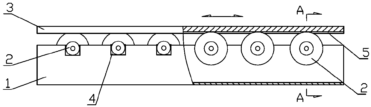
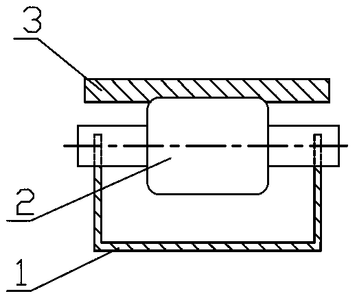
[0027] See figure 1 , figure 2 , is a structural schematic diagram of an embodiment of the roller-type transfer device of the present invention, including a trough-shaped base 1, a roller 2 and a slide plate 3, and more than three rollers 2 are arranged in parallel on the trough-shaped base 1, and the bottom of the slide plate 3 is carried on the rollers On the outer circle of 2, a groove 4 is provided at the edges of two sides along the length direction on the groove-shaped base 1, and the two ends of the roller 2 are carried on the groove 4.

[0028] In order to prevent the slide plate from falling off under force and causing a safety accident, a depression 5 is provided in the contact area between the bottom of the slide plate 3 and the roller 2, and the depth of the depression is 1 / 6-1 / 3 of the radius of the roller.

[0029] Since the movin...


PUM


Abstract

The invention relates to the technology of large motor assembly, in particular to a linear movement core sleeving assembly method of a large motor stator. The method is characterized in that the stator is placed on a roller type transferring device, is enabled to be capable of linearly moving along the roller type transferring device, and is pushed so as to complete core sleeving. The method includes the specific steps: 1) lifting the motor stator to be placed on the roller type transferring device; 2) temporarily connecting a rotor with an extended shaft; 3) disposing a first temporary support and a second temporary support; 4) lifting the rotor to penetrate the stator, and after the stator is penetrated, carrying the shaft end of the extended shaft on the first temporary shaft, and carrying the other end of the motor rotor on the second temporary shaft; 5) controlling the coaxiality of the stator and the rotor to be not larger than 5mm; and 6) moving the stator and completing core sleeving assembly. Compared with the prior art, the method has the advantages that general assembly of large motors of various specifications can be met, and vibration, swing and collision generated along with linear movement of the rotor in a core sleeving assembly process of the large motor are eliminated.

Description

technical field [0001] The invention relates to the field of assembling large-scale motors in industrial installation engineering of metallurgical systems, in particular to a method for assembling a large-scale motor stator linearly moving sleeve core. Background technique [0002] In enterprises without large-scale motor stator and rotor assembly equipment, the rotor is usually directly hoisted by a crane for core sleeve operation. The disadvantage is that there is vibration during the movement of the rotor, which is prone to collision between the stator and rotor magnetic poles, or high In case of a fall accident, the main steps of the operation process are as follows: [0003] Step 1: First fix the long shaft on the rotor, then put the stator at a position parallel to the crane trolley, lift the rotor by the crane, slowly insert the rotor into the stator, and the long shaft to be connected goes out of the other end of the stator , adjust the height of the center of the r...

Claims


Application Information

Patent Timeline
Patent Type & Authority Applications(China)
IPC IPC(8): H02K15/00
Inventor 姜长平邵波傅海李超李宏东
Owner ANGANG CONSTR CONSORTIUM
Why Eureka
Try Eureka