Negative pressure deslagging dredging core pipe valve

A negative pressure, water-repellent technology, applied in valve details, multi-port valves, valve devices, etc., can solve the problems of complex structure of slag discharger, unfavorable smooth discharge, small discharge diameter, etc., to improve reliability and long-term performance. , The effect of low manufacturing cost and long service life

Inactive Publication Date: 2018-10-02
卢星霖
View PDF6 Cites 0 Cited by
  • Summary
  • Abstract
  • Description
  • Claims
  • Application Information

AI Technical Summary

Problems solved by technology

[0005] The structure of the above-mentioned slag discharge water discharge device is too complicated and bulky. Among them, an atmospheric valve, a water discharge valve, a w

Method used


Image

  • Negative pressure deslagging dredging core pipe valve
  • Negative pressure deslagging dredging core pipe valve
  • Negative pressure deslagging dredging core pipe valve

Examples


Embodiment 1

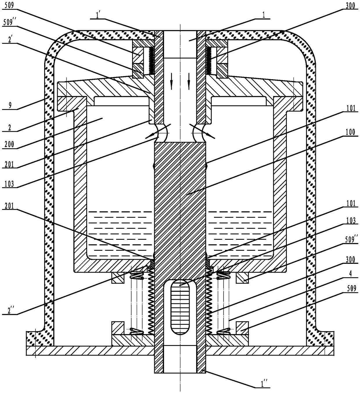
[0035] See attached figure 1 , 2 , the negative pressure slagging and draining core tube valve described in this embodiment, the valve core tube 1 is a sleeve tube I2' that runs through the valve body 2 from top to bottom, and the inner cavity of the valve body 2. 200, and the sleeve pipe II2" of the valve body 2; there is an axial partition 100 in the middle of the valve core pipe 1, and the partition 100 is composed of the inner core and the middle pipe section of the valve core pipe 1 radially radiating from the inner core; the axial two sides of the partition 100 They are respectively the two radial flow holes 103 of the input section 1' and the output section 1", wherein, the two flow holes 103 of the output section 1" are long and waist-shaped in the axial direction; The sealing surface of an annular spool 101 is a two-way slope and forms a sealing pair with the annular valve seat 201 of the throat of the sleeve pipe I2' and the sleeve pipe II2" respectively; the input ...

Embodiment 2

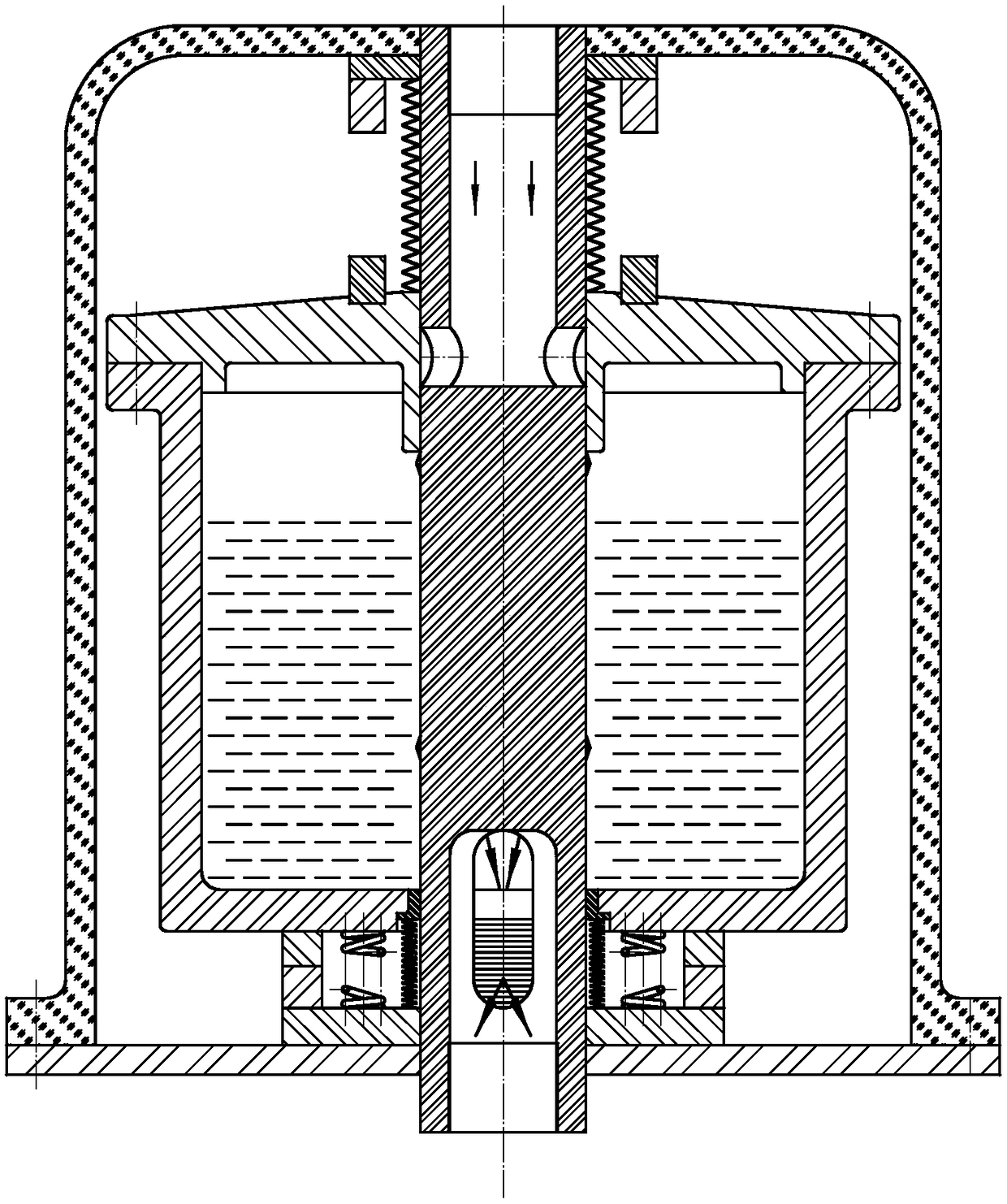
[0039] See attached image 3 , 4, the negative pressure slagging and draining core tube valve described in this embodiment, the valve core tube 1 is a sleeve tube I2' that runs through the valve body 2 from top to bottom, and the inner cavity of the valve body 2. 200, and the sleeve pipe II2" of the valve body 2; there is an axial partition 100 in the middle of the valve core pipe 1, and the partition 100 is composed of the inner core and the middle pipe section of the valve core pipe 1 radially radiating from the inner core; the axial two sides of the partition 100 The two radial flow holes 103 of the input section 1' and the output section 1" respectively; the sealing surfaces of the two annular spools 101 in the axial direction surrounding the partition 100 are circular arc slopes that are respectively connected to the sleeve tube I2' and the sleeve tube II2 The annular valve seat 201 of the "throat constitutes a sealing pair; the input section 1' and the sleeve pipe I2' a...

Embodiment 3

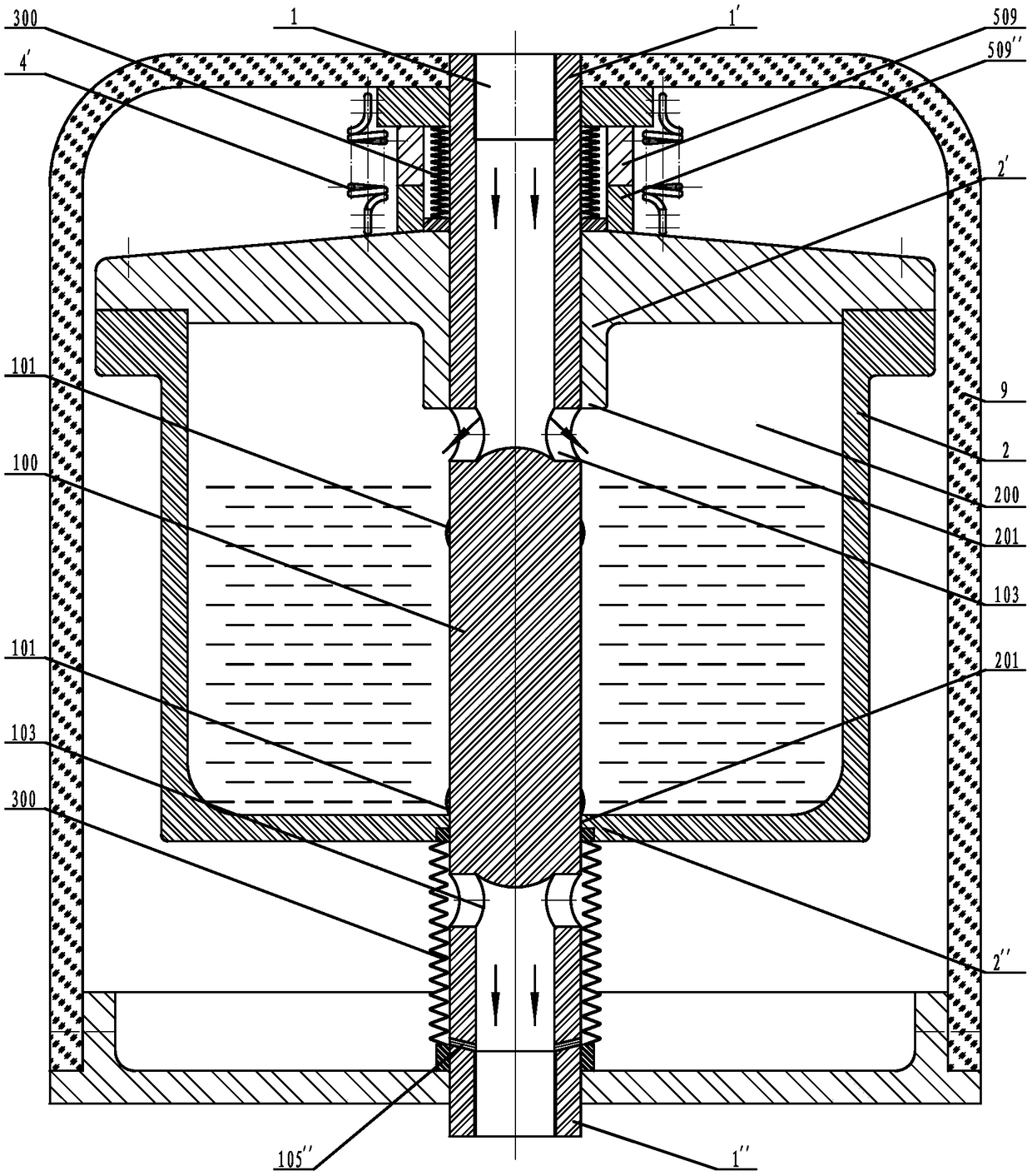
[0043] See attached Figure 5 , 6 , the negative pressure slagging and draining core tube valve described in this embodiment, the valve core tube 1 is a sleeve tube I2' that runs through the valve body 2 from top to bottom, and the inner cavity of the valve body 2. 200, and the sleeve pipe II2" of the valve body 2; there is an axial partition 100 in the middle of the valve core pipe 1, and the partition 100 is composed of the inner core and the middle pipe section of the valve core pipe 1 radially radiating from the inner core; the axial two sides of the partition 100 Two radial flow holes 103 of the input section 1' and the output section 1", wherein the two flow holes 103 of the output section 1" are long waists extending axially; the shaft surrounding and integrated with the partition 100 The sealing surfaces of the upper and lower annular spools 101 are one-way slope surfaces and respectively form a sealing pair with the annular valve seat 201 at the throat of the sleeve ...


PUM


Abstract

The invention discloses a negative pressure deslagging dredging core pipe valve, which is one of self-operated control valves of conventional core pipe valve plates in an original core pipe valve parent series. A valve core pipe is a fixed piece which is perpendicular to the ground surface, and coaxially penetrates through a sleeve I of a valve body, an inner cavity of the valve body and a sleeveII of the valve body from top to bottom; an axial partition layer is arranged in the middle of the valve core pipe; at least one radial circulating hole of each of an input section and an output section is formed in each of the two sides of the axial direction of the partition layer; an upper axial annular valve core and a lower axial annular valve core which surround the partition layer respectively form sealing pairs with annular valve seats at a throat part of each of the sleeve I and the sleeve II; the input section and the sleeve I as well as the output section and the sleeve II are in axial hole type fit, and at least one combination part is arranged in a sealed manner; a driving element which drives the valve body to travel upwards in the axial direction is arranged out of the valvebody; and under the action of liquid gravity and the driving element, the valve body moves reciprocally in the axial direction relative to the valve core pipe so as to realize discharging and closingof sludge and accumulated water. The negative pressure deslagging dredging core pipe valve is simple in structure, small in size, high in cost performance, large in discharging aperture and long in service life, and is flexible and reliable.

Description

technical field [0001] The negative pressure slagging and draining core tube valve of the present invention belongs to the field of valves, and is one of the self-operated control valves of the conventional core tube valve plate in the core tube valve mother series invented by myself; the negative pressure slagging and draining core tube valve It will replace the negative pressure slag discharge water release device, especially the mine negative pressure slag discharge water discharge device. Background technique [0002] There is a large amount of water and sediment in the coal mine gas pipe drainage system, which often causes pipeline blockage, poor drainage, increases the negative pressure of the system, increases the torque of the drainage motor, and greatly reduces the drainage efficiency, which makes the safety Production is seriously threatened. It is suitable for negative pressure automatic slag discharge and water discharge device for the main pipe, main pipe and b...

Claims


Application Information

Patent Timeline
IPC IPC(8): F16K11/07F16K31/08F16K31/44
CPCF16K11/0712F16K11/0716F16K31/0613F16K31/08F16K31/44
Inventor 卢星霖
Owner 卢星霖
Why Eureka
Try Eureka