
MMC (Modular Multi-level Converter) converter valve submodule device based on thyristor device and controlling method of submodule device

A thyristor and sub-module technology is applied to the MMC converter valve sub-module topology structure device and its control field based on thyristor devices, and can solve the problems of difficulty in balancing the voltage of sub-modules, increasing the number of sub-modules in series, and low rated voltage and current. , to achieve the effect of reducing control complexity, less series series, and large rated voltage and current

Active Publication Date: 2014-12-31
GLOBAL ENERGY INTERCONNECTION RES INST CO LTD +1
View PDF4 Cites 2 Cited by
  • Summary
  • Abstract
  • Description
  • Claims
  • Application Information

AI Technical Summary

Problems solved by technology

Compared with thyristor devices, IGBT devices have larger switching losses and complex control. The rated voltage and current of a single device is lower. With the continuous increase of voltage level, the number of sub-modules in series increases, and it is difficult to balance the voltage between sub-modules. , which is not conducive to the development of converter valves in the direction of high pressure and large capacity

Method used


Image

  • MMC (Modular Multi-level Converter) converter valve submodule device based on thyristor device and controlling method of submodule device
  • MMC (Modular Multi-level Converter) converter valve submodule device based on thyristor device and controlling method of submodule device

Examples


Embodiment Construction

[0032] The specific implementation manners of the present invention will be further described in detail below in conjunction with the accompanying drawings.

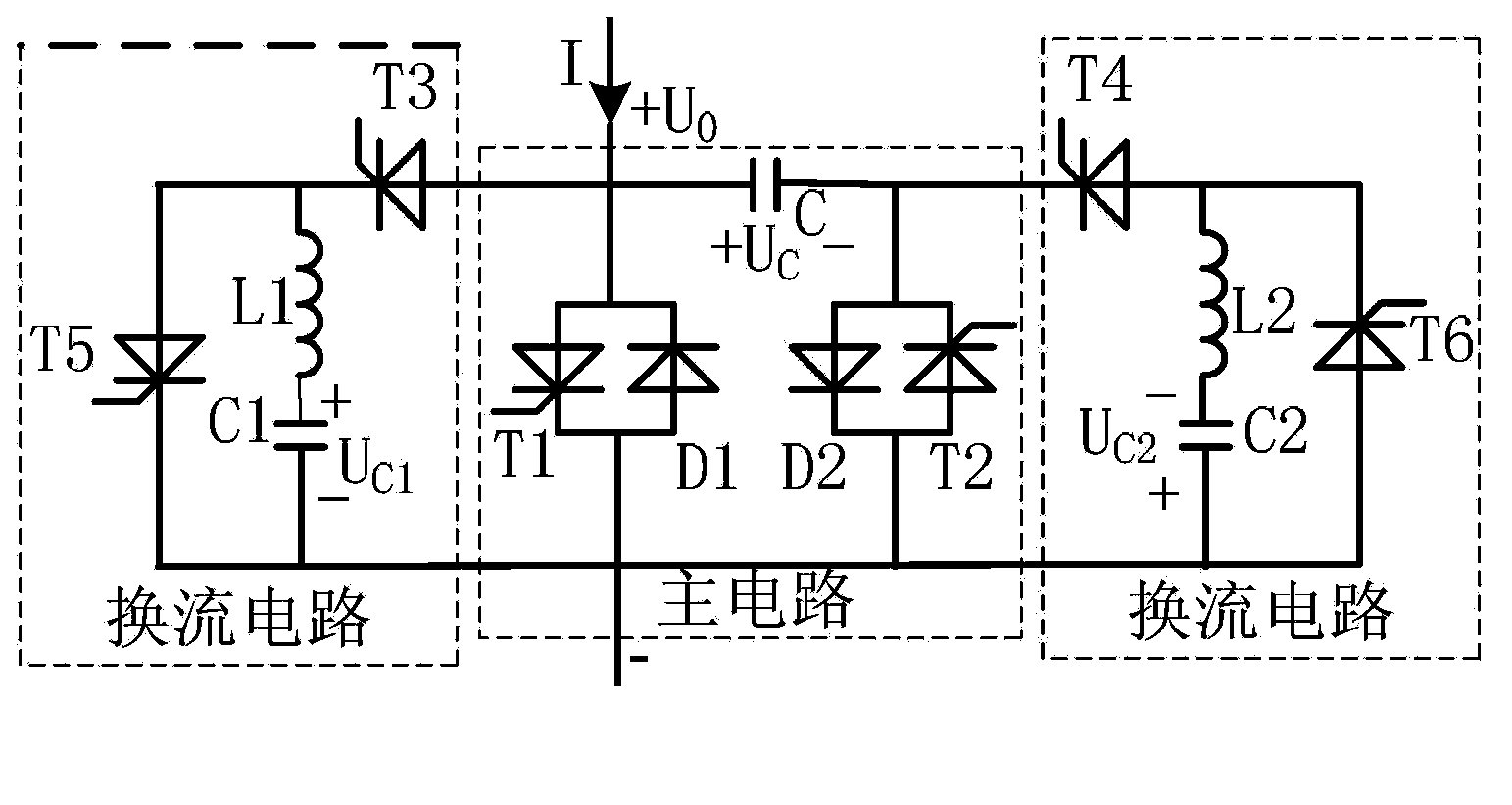
[0033] The topological structure of the MMC converter valve sub-module based on the thyristor device provided by the present invention is as follows: figure 2 As shown, it includes a main circuit and a forced commutation circuit connected in parallel with its two ends; the main circuit includes a thyristor unit I, a thyristor unit II and a capacitor C; both the thyristor unit I and the thyristor unit II are composed of a thyristor and a diode antiparallel to it .

[0034] The thyristor unit I is connected in parallel with the thyristor unit II; the capacitor C is connected between the thyristor unit I and the thyristor unit II.

[0035] The thyristor unit I includes a thyristor T1 and a diode D1 connected in antiparallel with it; the cathode of the thyristor T1 is connected to the anode of the diode D1, and the cathode...


PUM


Abstract

The present invention relates to the field of power systems and power electronics, in particular to a thyristor-device-based MMC converter valve submodule device and control method thereof. The device comprises a main circuit and forced commutation circuits in parallel connection with the two terminals of the main circuit; the main circuit comprises a thyristor unit I, a thyristor unit II, and a capacitor C; the thyristor unit I and the thyristor unit II are both comprised of a thyristor and a diode in inverse parallel connection with the thyristor. The method comprises the following steps: (1) respectively precharging a capacitor C1 and a capacitor C2 in the two forced commutation circuits; and (2) the submodule works and outputs a voltage. The thyristor-device-based MMC converter valve submodule structure utilizes a thyristor device to replace an IGBT device, thus reducing the switching loss of the device, reducing control complexity, and improving the transformation efficiency of the submodule.

Description

technical field [0001] The present invention relates to the field of power system and power electronics, in particular to a thyristor device-based MMC converter valve sub-module device and its control method, in particular to a thyristor-based MMC converter valve sub-module topology device and its control method. Background technique [0002] Due to the shortage of energy and the deterioration of the environment, vigorously developing new energy has become the main direction of my country's development, and flexible direct current transmission technology is the main means of grid-connected new energy. The core equipment of the flexible DC transmission technology, the voltage source control (VSC) converter valve, currently mainly adopts a modular multilevel (MMC) structure, which firstly consists of sub-modules that can be turned off, and then multiple sub-modules are connected in series. [0003] The structure of the sub-module is very important to the performance and contr...

Claims


Application Information

Patent Timeline
Patent Type & Authority Patents(China)
IPC IPC(8): H02M3/10
CPCH02M7/003H02M7/483H02M2007/4835H02M7/4835
Inventor 温家良王秀环郭高鹏吴婧王宇杨杰药涛
Owner GLOBAL ENERGY INTERCONNECTION RES INST CO LTD
Learn More