
Fixed-length time slot based dynamic channel allocation method for time division duplex/time division multiple access

A time-division multiple access and time-division duplex technology, which is applied in the field of communication, local area network and access network, can solve the problems of low channel utilization, high complexity of channel allocation scheduling algorithm, large data transmission waiting delay, etc., to reduce Requirements for equipment operating speed, requirements for reducing complexity, and the effect of high channel utilization efficiency

Active Publication Date: 2015-07-15
XIDIAN UNIV +3
View PDF4 Cites 0 Cited by
  • Summary
  • Abstract
  • Description
  • Claims
  • Application Information

AI Technical Summary

Problems solved by technology

[0005] The static channel allocation method has the problem of low channel utilization. Each fixed-size time slot is assigned to a certain node for data transmission. If the node has no data to transmit for a certain period of time, the allocation The time slot given to the node is wasted
When the network service changes frequently, the situation of low channel utilization will be very serious
[0006] The fully dynamic channel allocation method has problems such as high complexity of the scheduling algorithm for channel allocation, too complex planning frame, too high requirements for the operating speed of the realization equipment, and too large waiting delay for data transmission.
First of all, the length of each time slot and the nodes using the time slot in the dynamic allocation method are dynamically variable, which itself requires a relatively complex scheduling algorithm for channel allocation; secondly, in order to ensure that the scheduling algorithm can run normally , the central node needs to issue the channel planning scheme for the next planning cycle to each slave node through the planning frame containing detailed information such as the start and end time of each time slot, the length of the time slot, and the user. The length of each planning cycle, the number of time slots The number of time slots and the length of each time slot may be different, and the generation and analysis of planning frames are more complicated; finally, due to the fine dynamic planning of the use of time slots for each node, the central node needs to perform channel planning once in each planning cycle. Complicated scheduling planning, and generating and sending the planning frame before the next planning cycle takes effect, this puts forward high requirements on the operating speed of the central node, the higher the channel rate, the higher the requirement; in order to reduce the central node The requirement of node computing speed can increase the planning period, but this will increase the waiting delay of data transmission

Method used


Image

  • Fixed-length time slot based dynamic channel allocation method for time division duplex/time division multiple access
  • Fixed-length time slot based dynamic channel allocation method for time division duplex/time division multiple access
  • Fixed-length time slot based dynamic channel allocation method for time division duplex/time division multiple access

Examples


Embodiment 1

[0028] In this example, the network is composed of central node 0 and slave nodes 1 and 2; the physical layer is modulated by OFDM, the duration of one OFDM symbol is 18us, the length of the physical frame header is 2us, and the time slots between adjacent uplink (or downlink) time slots The interval between time slots is 2us, and the frame interval between sending and receiving transitions between the down (up) time slot and the adjacent up (down) time slot is 50 us.

[0029] The planning frame is sent by the central node, which contains the channel allocation scheme in the next planning period and the confirmation information of the uplink data frame in the previous planning period. The planning frame is carried by a physical frame of one OFDM symbol and broadcast by the central node to all slave nodes .

[0030] The report frame is sent by the slave node, which contains the local queue information of the slave node and the confirmation information of the downlink data frame...

Embodiment 2

[0123] Embodiment 2 In this example, the network is composed of central node 0 and slave nodes 1 and 2; the physical layer is modulated by OFDM, the duration of one OFDM symbol is 18us, the length of the physical frame header is 2us, and the adjacent uplink (or downlink) each The time slot interval between the slots is 2us, and the frame interval between sending and receiving conversion between the down (up) line time slot and the adjacent up (down) line time slot is 50 us.

[0124] The planning frame is sent by the central node, which contains the channel allocation scheme in the next planning period and the confirmation information of the uplink data frame in the previous planning period. The planning frame is carried by a physical frame of one OFDM symbol and broadcast by the central node to all slave nodes .

[0125] The report frame is sent by the slave node, which contains the local queue information of the slave node and the confirmation information of the downlink data...


PUM


Abstract

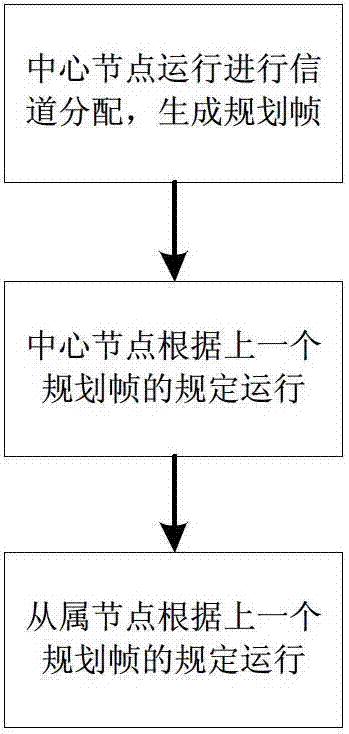
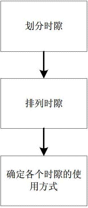
The invention discloses a fixed-length time slot based dynamic channel allocation method for time division duplex / time division multiple access. The method mainly solves the problems of insufficient channel utilization rate or complexity of a scheduling algorithm and a planning frame, too high requirement on equipment and the like of an existing channel allocation method. The method includes the implementation steps: performing channel allocation once every a plurality of planning cycles by a central node, namely dividing the planning cycles into various fixed-length time slots; arranging the time slots according to the fixed sequence; dynamically determining a utilization method of each time slot, and presenting the utilization methods into a planning frame; enabling slave nodes to use various time slots according to stipulations of a previous planning frame; and enabling the central node to use various time slots according to stipulation of the previous planning frame. The fixed-length time slot based dynamic channel allocation method for time division duplex / time division multiple access is high in channel utilization rate, simple in scheduling algorithm and planning frame and low in requirement on equipment, and can be applied to the field of various local area networks and access networks adopting time division duplex / time division multiple access communication.

Description

technical field [0001] The invention belongs to the technical field of communication, and relates to a time division duplex / time division multiple access channel dynamic allocation method based on a fixed-length time slot, which can be applied to various local area networks and access network fields using time division duplex / time division multiple access communication. Background technique [0002] In LANs and access networks based on shared media, in order to achieve reasonable and conflict-free allocation of channel resources, a central point-to-multipoint logical topology is often used. In this network structure, there is a central site that uniformly allocates the use of channel resources, and other sites except the central site are called slave nodes. Data communication can be directly performed between the central site and the subordinate sites, and the communication between the subordinate sites generally needs to be forwarded through the central site. The central n...

Claims


Application Information

Patent Timeline
Patent Type & Authority Patents(China)
IPC IPC(8): H04L12/917H04L47/76
Inventor 张冰邱智亮颜克洲李红滨张奭张诚赵辉孙汉汶
Owner XIDIAN UNIV
Learn More