Coding and decoding method and device in optical communication

An encoding method and optical communication technology are applied in the field of encoding and decoding of signals transmitted inside optical communication equipment, and can solve the problem of low utilization rate of communication channels.

Active Publication Date: 2020-10-23
HUAWEI TECH CO LTD
View PDF9 Cites 0 Cited by
  • Summary
  • Abstract
  • Description
  • Claims
  • Application Information

AI Technical Summary

Problems solved by technology

[0005] In the prior art, the number of optical modules connected to the OLT is large, and various signals need to be transmi...

Method used


Image

  • Coding and decoding method and device in optical communication
  • Coding and decoding method and device in optical communication
  • Coding and decoding method and device in optical communication

Examples


Embodiment Construction

[0043] Before elaborating the solutions provided by the embodiments of the present application in detail, in order to facilitate understanding of the technical solutions provided by the embodiments of the present application, the related technologies and concepts involved in the embodiments of the present application are firstly introduced.

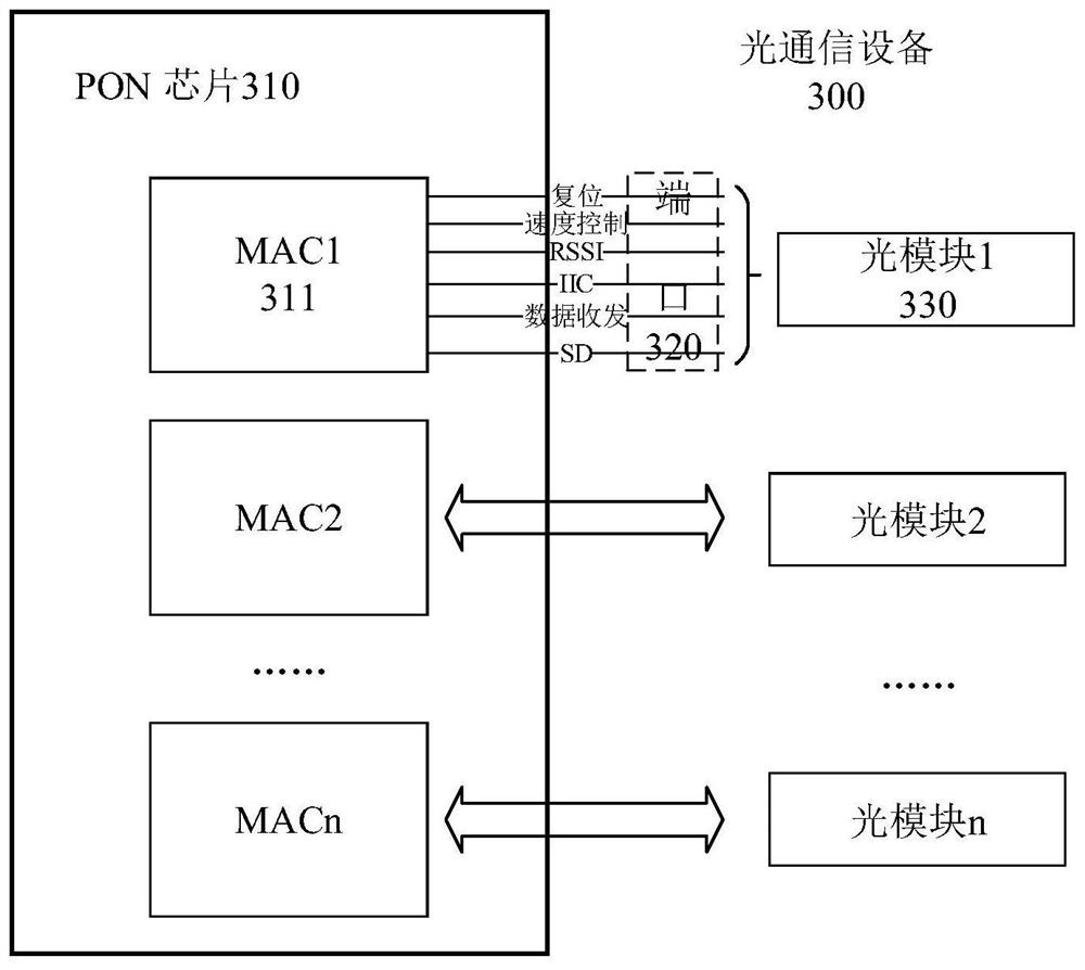
[0044] 1. Signals that need to be transmitted between the optical module and the PON chip: various signals need to be sent between the optical module and the PON chip, such as data signals carrying uplink and downlink business data between optical communication devices, as well as I2C signals, Rx_SD, Tx_Fault, On_Line , Power_On, Reset, Rate_Select, Tx_Disable, RSSI_Triger and other control signals. Among them, the business data is the data that the optical communication equipment needs to transmit to other optical communication equipment through the optical module, and the control signal is used to transmit the status and control informat...


PUM


Abstract

The embodiment of the invention provides a coding and decoding method for optical communication. According to the method, signals transmitted between a communication chip and an optical module are divided into three types of data signals, delay signals and real-time signals according to different bearing information and real-time requirements, the delay signals are encoded into control data, and the control data and service data are multiplexed into one channel for transmission. Meanwhile, the level jump condition of the real-time signals, the control data and the service data are uniformly encoded and then transmitted. By utilizing the encoding and decoding method provided by the embodiment of the invention, multiple paths of signals can be transmitted by adopting one line, the signal transmission efficiency and the line utilization rate are effectively improved, the number of pins of the communication chip can be reduced, and the size of the communication chip is further reduced. Inaddition, due to the fact that communication lines are reduced, interference among all paths of signals can be reduced.

Description

technical field [0001] The present application relates to the field of optical communication, and in particular to a method and device for encoding and decoding internal transmission signals of optical communication equipment. Background technique [0002] With the continuous enrichment of multimedia services, the demand for access network bandwidth is increasing. In this case, the application of passive optics network (PON) is becoming wider and wider. It can provide long-distance, Large bandwidth access, which cannot be achieved by traditional asymmetric digital subscriber line (ADSL). [0003] PON refers to a passive electronic device consisting of an optical line terminal (OLT) as a central office device, an optical network unit (ONU) as a terminal device, and an optical distribution network (ODN) system. Wherein, the OLT and the ONU may be collectively referred to as an optical communication device, and the optical communication device includes a PON chip and an optic...

Claims


Application Information

Patent Timeline
IPC IPC(8): H04B10/25H04B10/516H04Q11/00
CPCH04Q11/0067H04B10/25H04B10/516
Inventor 薛建林李豫西聂世玮
Owner HUAWEI TECH CO LTD
Why Eureka
Try Eureka