
Heat radiation structure and back board used by heat radiation structure

A technology of heat dissipation structure and heat dissipation bottom plate, which is applied in the direction of cooling/ventilation/heating transformation, electrical components, electric solid devices, etc. It can solve the problems of increasing the time for the assembler to assemble the heat dissipation module, difficult control of assembly force, and labor cost. , to achieve the effect of saving labor costs, easy disassembly and assembly, and time saving

Inactive Publication Date: 2013-04-03
SY THERMAL
View PDF8 Cites 1 Cited by
  • Summary
  • Abstract
  • Description
  • Claims
  • Application Information

AI Technical Summary

Problems solved by technology

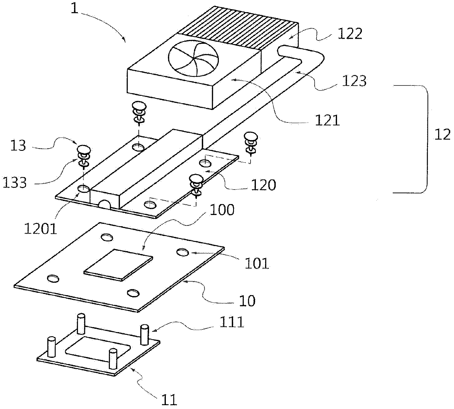
Generally speaking, the existing technology still has the following disadvantages that need to be improved: (1) There are a large number of parts to be assembled, and the assembly method is relatively complicated. In addition to increasing the time for the assembler to assemble the heat dissipation module, it also costs a lot of parts; ( 2) Manual assembly is required, which consumes labor costs; (3) It is difficult to control the assembly force; and (4) When the chip or heat dissipation module needs to be replaced or repaired, it is not easy to disassemble and assemble

Method used


Image

  • Heat radiation structure and back board used by heat radiation structure
  • Heat radiation structure and back board used by heat radiation structure
  • Heat radiation structure and back board used by heat radiation structure

Examples


Embodiment Construction

[0043] In order to make the above-mentioned purpose, features and advantages of the present invention more obvious and easy to understand, according to the heat dissipation structure and the backplane used in the present invention, preferred embodiments are specifically cited below, and are described in detail as follows in conjunction with the attached related drawings .

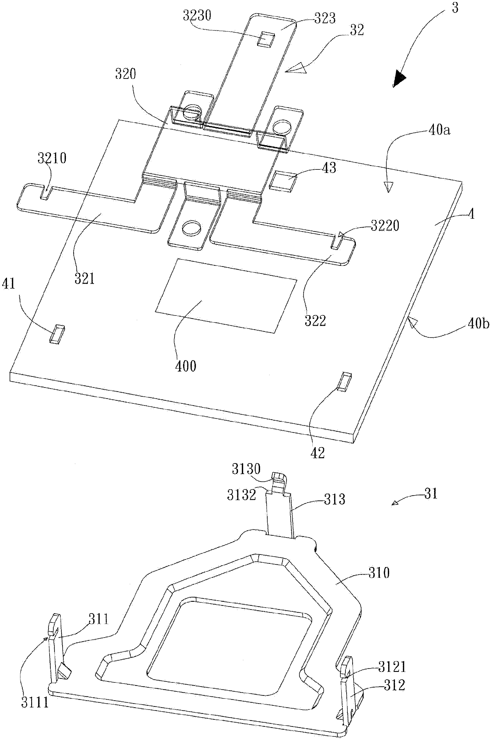
[0044] Please refer to Figure 3A , is the heat dissipation structure 3 of the embodiment of the present invention. The heat dissipation structure 3 is fixed on a circuit board 4 in an engaging manner, and is used to dissipate a chip 400 on the upper surface 40a of the circuit board 4. Around the chip 400, a first positioning hole 41, a second positioning hole 42 and a The third positioning hole 43 . The heat dissipation structure 3 includes a back plate 31 and a heat dissipation bottom plate 32 .

[0045] The back plate 31 is arranged on the lower surface 40b of the circuit board 4 and combined with a h...


PUM


Abstract

The invention provides a heat radiation structure and a back board used by the heat radiation structure. The back board is combined with a radiating base plate in a clamping mode, and the radiating base plate is positioned on the upper surface of a circuit board. A chip is arranged on the upper surface of the circuit board; a plurality of positioning holes are formed around the chip; the radiating base plate is attached to the chip; the back board comprises a plurality of supporting columns, and each supporting column is provided with a clamping mechanism which is selected from a clamping hook, a clamping groove or a clamping hole; besides, at least one of the supporting column is provided with an elastic clamping mechanism, and these supporting columns penetrate through the positioning holes from the lower surface of the circuit board and protrude upwards; and during clamping, the radiating base plate is clamped on the supporting columns from top to bottom. Therefore, the heat radiation structure has a simple assembly way and is easy to assemble and disassemble.

Description

technical field [0001] The present invention relates to a heat dissipation module, in particular to a heat dissipation structure with a simple assembly method and easy disassembly and assembly between the heat dissipation bottom plate and the fixed structure of the back plate, and the back plate used therein. Background technique [0002] With the advancement of science and technology, many portable electronic products, such as notebook computers, tend to be lighter and thinner to meet the needs of users for easy portability. It is well known that the central processing chip (CPU) inside the electronic product will generate a large amount of heat energy during operation, which will increase the temperature. Therefore, after the thinning of the electronic product, how to quickly dissipate the large amount of heat accumulated in the chip in an effective space It is the focus of active research and development of personnel in this technical field. [0003] Please refer to fig...

Claims


Application Information

Patent Timeline
Patent Type & Authority Applications(China)
IPC IPC(8): H05K7/20H01L23/40
Inventor 郭昭正陈峰萧复元郑学隆
Owner SY THERMAL
Learn More