Decoupling of multiple channels of an MRI RF coil array

A decoupling, radio frequency coil technology, applied in the field of multi-channel radio frequency coil components, can solve the problems of influence, difficult adjustment of passive decoupling network, mutual coupling influence, etc., to reduce manufacturing time and cost, reduce decoupling adjustment time, The effect of increasing the number

Active Publication Date: 2013-04-03
KONINKLIJKE PHILIPS ELECTRONICS NV
View PDF11 Cites 19 Cited by
  • Summary
  • Abstract
  • Description
  • Claims
  • Application Information

AI Technical Summary

Problems solved by technology

At high field strengths, small changes in load can have a significant effect on mutual coupling
Known passive decoupling networks are also difficult to tune because a single de...

Method used


Image

  • Decoupling of multiple channels of an MRI RF coil array
  • Decoupling of multiple channels of an MRI RF coil array
  • Decoupling of multiple channels of an MRI RF coil array

Examples


Embodiment Construction

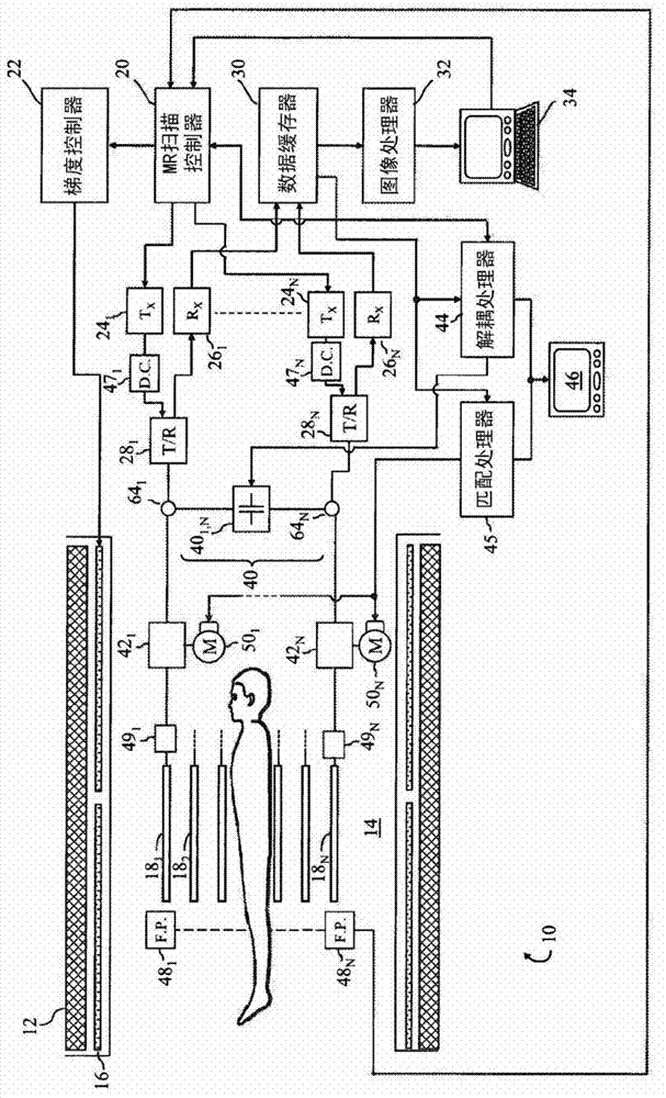
[0024] refer to figure 1 , a magnetic resonance (MR) imaging system 10 includes a main magnet 12 that generates a spatially and temporally uniform B through an examination region 14 0 field. The main magnet can be a ring or bore magnet, a C-shaped open magnet, other designs of open magnet, etc. The gradient magnetic field coil 16 arranged adjacent to the main magnet is used to move along the 0 Selected axes of the magnetic field generate magnetic field gradients for spatially encoding the magnetic resonance signals, for generating magnetization disturbance field gradients, and the like. Magnetic field gradient coils 16 may include coil segments configured to generate magnetic field gradients in three orthogonal directions, typically a longitudinal or z direction, a transverse or x direction, and a vertical or y direction.

[0025] A radio frequency (RF) coil assembly 18, such as a whole body radio frequency coil, is disposed adjacent the examination region. The RF coil ass...


PUM


Abstract

A radio-frequency coil assembly (18), for use in a magnetic resonance imaging system (10), includes a plurality of coil elements (18n). The coil elements (18n) are connected to a decoupling network (40) which includes a plurality of decoupling elements (40n,x) connected (via transmission lines) to pairs of coil elements (18n, 18x) at corresponding ports (64n,64x) from which the coil can be fed. The decoupling elements (40n,x) compensate for mutual coupling between pairs of corresponding coil elements. An inductive coupling loop (51n), with a constant or adjustable mutual inductance, inductively couples the associated coil element (18n) to the corresponding decoupling network port (64n). Transmission lines (52n) electrically connect each inductive coupling loop (51n) to the decoupling network (40) at the corresponding port (64x). Each transmission line (52n) has an electrical length of k[lambda]/2 where k=0,1,2,3 . . . and [lambda] is a wavelength of the excited and/or received resonance signals inside the transmission line.

Description

technical field [0001] This application relates to the field of magnetic resonance. This application is particularly applicable to, and will be described with particular reference to, multi-channel radio frequency coil assemblies. Background technique [0002] Magnetic resonance imaging (MRI) and spectroscopy (MRS) systems are often used in the examination and management of patients. With this system, the nuclear spins of the body tissue to be examined are aligned by the static main magnetic field B0 and excited by the transverse magnetic field B1 oscillating in the radio frequency band. In imaging, the relaxation signal is exposed to a gradient magnetic field to localize the nuclear spins. The relaxation signal is received to form a single or multi-dimensional image by known means. In spectroscopic analysis, information about tissue composition is carried in the frequency components of the resonance signal. [0003] Two types of MR systems commonly used include "open" M...

Claims


Application Information

Patent Timeline
IPC IPC(8): G01R33/36
CPCG01R33/3642G01R33/365G01R33/3415
Inventor C·芬德科里
Owner KONINKLIJKE PHILIPS ELECTRONICS NV
Why Eureka
Try Eureka