Improved bed clapboard

A clapboard and strip board technology, applied in the field of furniture, can solve the problems of poor air permeability and easy breeding of bacteria in bed partitions, and achieve the effect of improving air permeability and sleeping comfort, simple structure, and easy realization

Inactive Publication Date: 2013-04-10
王芳
9 Cites 0 Cited by

AI-Extracted Technical Summary

Problems solved by technology

[0003] The purpose of the present invention is to provide an improved bed partition to solve t...

Abstract

The invention discloses an improved bed clapboard, which comprises a frame body composed of four frames. A plurality of longitudinal strip plates are connected in the frame body, and a plurality of cross barrier bars are transversely arranged in the frame body. The cross barrier bars are arranged at the lower parts of the strip plates, and reinforced bars are connected between adjacent frames in the frame body. Connecting seats are arranged at four vertex angle positions of the rear surface of the frame body. The air permeability and the sleep comfort of the bed clapboard can be obviously increased, and the bed clapboard is not easy to breed bacteria. Meanwhile, the reinforced bars are arranged in the frame body and the connecting seats are arranged at the vertex angle positions of the outer part of the frame body, the bed clapboard is not easy to deform after use for long term and can be disassembled and assembled conveniently. The bed clapboard has a simple structure and is easily realized.

Application Domain

Bedstands

Technology Topic

EngineeringBacteria

Image

  • Improved bed clapboard
  • Improved bed clapboard

Examples

  • Experimental program(1)

Example Embodiment

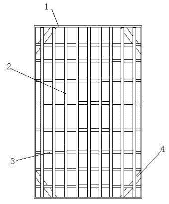
[0010] Examples such as figure 1 , figure 2 As shown, an improved bed divider, a frame body composed of 4 frames 1, in which a plurality of longitudinally arranged long strips 2 are connected, and a plurality of horizontally arranged horizontally arranged in the frame body The stop rod 3 and the cross stop rod 3 are arranged at the lower part of the strip plate 2, the adjacent frames 1 in the frame body are connected with reinforcing rods 4, and the four corner positions behind the frame body 1 are provided with connecting seats 5 .
[0011] The above embodiments only describe the preferred embodiments of the present invention, and do not limit the scope of the present invention. Without departing from the design spirit of the present invention, those of ordinary skill in the art have made various contributions to the technical solutions of the present invention. Variations and improvements should fall within the protection scope determined by the claims of the present invention.
[0012] The parts not involved in the present invention are the same as the prior art or can be implemented by the prior art.

PUM

no PUM

Description & Claims & Application Information

We can also present the details of the Description, Claims and Application information to help users get a comprehensive understanding of the technical details of the patent, such as background art, summary of invention, brief description of drawings, description of embodiments, and other original content. On the other hand, users can also determine the specific scope of protection of the technology through the list of claims; as well as understand the changes in the life cycle of the technology with the presentation of the patent timeline. Login to view more.

Similar technology patents

Gripping apparatus of tubular pile steel cage

InactiveCN101717036AUniform force pointNot easily deformed
Owner:GUANGDONG SANHE PILE CO LTD

Light guide element and backlight module

InactiveCN105090892ANot easily deformed
Owner:WUHAN CHINA STAR OPTOELECTRONICS TECH CO LTD

Classification and recommendation of technical efficacy words

Why Eureka
Try Eureka