Muscle driving simulation robot joint

A technology of robot joints and muscles, applied in the field of imitated muscle-driven robot joints, can solve the problems of low positioning accuracy, large driving force, easy to generate vibration, etc., and achieve the effect of simple joint structure, large working space and flexible movement.

Inactive Publication Date: 2013-04-10
NORTHEASTERN UNIV
View PDF12 Cites 7 Cited by
  • Summary
  • Abstract
  • Description
  • Claims
  • Application Information

AI Technical Summary

Problems solved by technology

[0003] 1. The robot joint is based on the parallel counter-driven pneumatic artificial muscles. The joint uses two pneumatic artificial muscles to provide the driving force. The driving force is large but the positioning accuracy is low, and it is easy to generate vibration during the movement
[0004] 2. The robot joint based on the parallel counter-drive of the rotating motor is characterized by large driving force and high precision, but the structure of the joint part is relatively complicated and a winding device needs to be installed
[0005] 3. The robot joint based on the piezoelectric actuator parallel counter-driven, although the joint has the advantages of simple structure and small size, but the driving force is also small, so it is only suitable for driving small joints
[0006] The above three types of existing robot joint mechanisms still have many limitations in imitating human joint movements.

Method used


Image

  • Muscle driving simulation robot joint
  • Muscle driving simulation robot joint
  • Muscle driving simulation robot joint

Examples


Embodiment 1

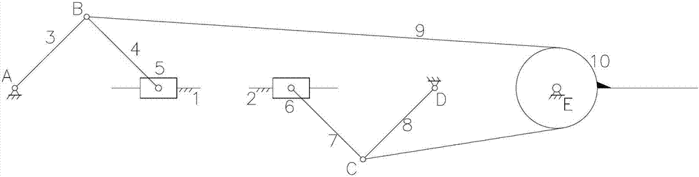
[0025] As shown in Figure 1, a robot joint driven by imitation muscles includes a rear crank slider mechanism, a front crank slider mechanism and a fixed pulley 10, and the rear crank slider mechanism is provided with a rear frame fixed Connected linear guide rail 1, rear slide block 5 is installed on described rear mount rack fixedly connected linear guide rail 1, and described rear mount slide block 5 links to each other with one end of rear mount connecting rod 4; One end of the rear fixed axis rotating crank 3 is installed at the center of rotation A, and the other end of the rear connecting rod 4 is connected with the other end of the rear fixed axis rotating crank 3; the front crank slider mechanism The front rack fixed linear guide rail 2 is provided, and the front slider 6 is installed on the front rack fixed linear guide rail 2. The front slider 6 and one end of the front connecting rod 7 Connected; one end of the front fixed-axis rotating crank 8 is installed at the ...

Embodiment 2

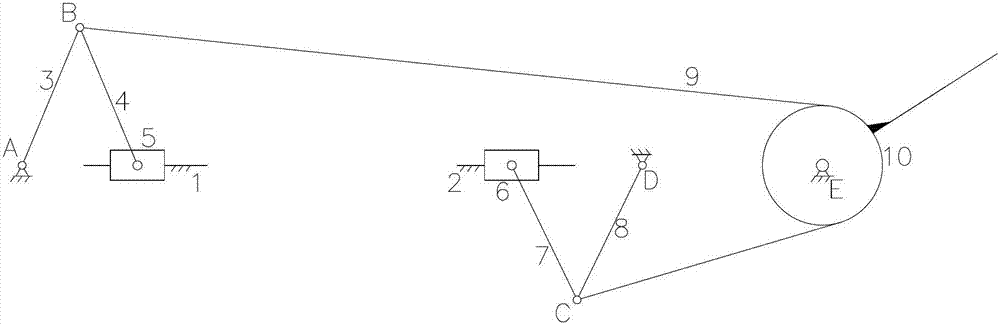
[0028] like Figure 5 As shown, a robot joint driven by imitation muscles includes a rear crank slider mechanism, a front crank slider mechanism and a fixed pulley 10, and the rear crank slider mechanism is provided with a rear rack fixed linear guide rail 1. A rear slider 5 is installed on the fixed linear guide rail 1 of the rear rack, and the rear slider 5 is connected to one end of the rear connecting rod 4; The head end of the rear fixed-axis rotating crank 3 is installed at the place, and the other end of the rear-mounted connecting rod 4 is connected with the end of the rear fixed-axis rotating crank 3; the front crank slider mechanism is provided with a front Set the rack fixed linear guide rail 2, the front slide block 6 is installed on the front rack fixed linear guide rail 2, and the front slide block 6 is connected with one end of the front connecting rod 7; The head end of the front fixed-axis rotating crank 8 is installed at the center of rotation of the front f...

Embodiment 3

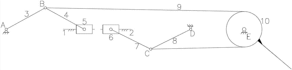
[0031] like Figure 4 As shown, a robot joint driven by imitation muscles includes a rear crank slider mechanism, a front crank slider mechanism and a fixed pulley 10, and the rear crank slider mechanism is provided with a rear rack fixed linear guide rail 1. A rear slider 5 is installed on the fixed linear guide rail 1 of the rear rack, and the rear slider 5 is connected to one end of the rear connecting rod 4; The head end of the rear fixed-axis rotating crank 3 is installed at the place, and the other end of the rear-mounted connecting rod 4 is connected with the end of the rear fixed-axis rotating crank 3; the front crank slider mechanism is provided with a front Set the rack fixed linear guide rail 2, the front slide block 6 is installed on the front rack fixed linear guide rail 2, and the front slide block 6 is connected with one end of the front connecting rod 7; The head end of the front fixed-axis rotating crank 8 is installed at the center of rotation of the front f...


PUM


Abstract

The invention discloses a muscle driving simulation robot joint, which belongs to the technical field of the biomimetic robot joint. The invention particularly relates to the muscle driving simulation robot joint which consists of a double-crank sliding block mechanism and is similar to the human muscle confrontation driving characteristic. The muscle driving simulation robot joint has the advantages of flexible action, big working space and simple structure and can be used for simulating the human muscle rigidity nonlinear driving. The muscle driving simulation robot joint comprises a rear crank sliding block mechanism, a front crank sliding block mechanism and a fixed pulley, wherein the rear crank sliding block mechanism and the front crank sliding block mechanism are respectively provided with a fixedly-connected linear guide rail for a rack; the fixedly-connected linear guide rail for the rack is provided with a sliding block; the sliding block is connected with one end of a connecting rod; the rotating center of the rack is provided with the first end of a fixed shaft rotating crank; the other end of the connecting rod is connected with the tail end of the fixed shaft rotating crank; the rotating center of the fixed pulley is provided with the fixed pulley; the fixed pulley is provided with a soft rope; and two ends of the soft rope are respectively connected with the junction of a rear fixed shaft rotating crank and a rear connecting rod as well as the junction of a front fixed shaft rotating crank and a front connecting rod.

Description

technical field [0001] The invention belongs to the technical field of bionic robot joints, and in particular relates to a robot joint driven by imitation muscles, which is composed of a double-crank slider mechanism and is similar to human muscle resistance driving characteristics. Background technique [0002] Human joints have the characteristics of flexible movement, light weight and high output force. The robot joints driven by parallel confrontation are more and more paid attention to by researchers because the driving mode is consistent with the principle of human joint action, and it is convenient to simulate the action characteristics of human joints. How to make robot joints imitate the action principle and action characteristics of human joints to the greatest extent, so that they have similar functional characteristics to human joints, has always been the goal of researchers. Among the robot joints that have emerged in recent years using parallel confrontation d...

Claims


Application Information

Patent Timeline
Patent Type & Authority Applications(China)
IPC IPC(8): B25J17/02
Inventor 房立金刘振豪
Owner NORTHEASTERN UNIV
Why Eureka
Try Eureka