Automobile seat chair slide rail with improved structure

A technology for car seat slide rail and structure improvement, which is applied in the direction of movable seats, etc., and can solve the problem of difficult control of sliding force consistency and synchronization in the gap between slide rails, high requirements for parts processing precision, and high requirements for parts processing precision, etc. problem, to achieve the effect of eliminating shaking gap, low production cost and reliable strength

Inactive Publication Date: 2013-04-10
JIANGSU ZHONGMING XIANGHE SEIKO
View PDF6 Cites 19 Cited by
  • Summary
  • Abstract
  • Description
  • Claims
  • Application Information

AI Technical Summary

Problems solved by technology

However, the following problems have been exposed in the actual use process: 1. Because there is a gap in the middle of the upper guide rail, there are certain limitations in the strength of the slide rail and the front and rear clearance; 2. Because the bead frame is a metal part, the slide rail is in the There are abnormal noises during the sliding process; 3. Since the upper guide rail slides relative to the lower guide rail through the rolling of the rollers and balls, the machining accuracy of the parts is required to be high, and the clearance of the slide rails, the consistency and synchronization of the sliding force are difficult to control ;4. Because there are lock grooves directly on both sides of the wrench and correspond to the locking teeth, the processing accuracy of the parts is required to be high

Method used


Image

  • Automobile seat chair slide rail with improved structure
  • Automobile seat chair slide rail with improved structure
  • Automobile seat chair slide rail with improved structure

Examples


Embodiment Construction

[0019] In order to enable the examiners of the patent office, especially the public, to understand the technical essence and beneficial effects of the present invention more clearly, the applicant will describe in detail below in conjunction with the accompanying drawings in the form of embodiments, but none of the descriptions of the embodiments is a description of the present invention. Restriction of the inventive solution, any equivalent transformation made according to the concept of the present invention which is only in form but not in substance shall be regarded as the scope of the technical solution of the present invention.

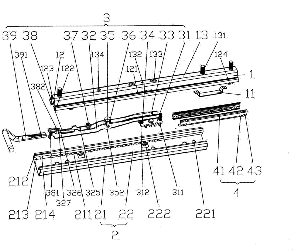
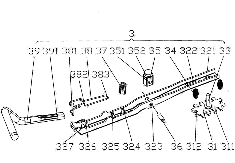
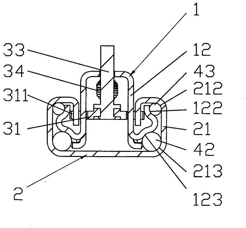
[0020] Please refer to figure 1 and combine figure 2 , image 3 and Figure 4 , a car seat slide rail with improved structure in the present invention, including a lower guide rail 2 for connecting with the car floor, an upper guide rail for connecting with the car seat and slipping on the lower guide rail 2 through a bead frame 4 1,...


PUM


Abstract

The invention relates to an automobile seat chair slide rail with an improved structure, and belongs to the technical field of automobile fittings. The automobile seat chair slide rail comprises a lower guide rail, an upper guide rail and a locking device, wherein the upper guide rail is in sliding fit with the lower guide rail by ball brackets, the upper guide rail is provided with lock claw grooves which are respectively in an inclined cut shape, a reinforcing bracket is additionally arranged under an upper mounting surface, the upper guide rail and the lower guide rail are respectively provided with a circular arc-shaped raceway accommodating cavity, large steel balls and small steel balls of the ball brackets roll on the circular arc-shaped raceway accommodating cavities, the insides of one pair of folding edges of the lower guide rail are provided with lock row teeth, the locking device comprises a lock block, a wrench, a connecting pin, a pull spring, a fixed block, a rotary shaft, a press spring, a wrench spring and a connecting pipe, the lock block is provided with lock claws which are matched with the lock claw grooves and the locked row teeth, the lock block is fixedly arranged on the wrench, and the wrench is arranged between the upper guide rail and the lower guide rail. The automobile seat chair slide rail has the advantages that the locking strength is high, the synchronism is high, the self-locking is avoided, the clearance is small, the sliding uniformity is high, the shaking clearance of the wrench is small, and the abnormal noise in sliding is avoided; and meanwhile, the processing and the manufacturing are convenient, the production cost is low, and the application range is wide.

Description

technical field [0001] The invention relates to a structurally improved slide rail for a car seat, which is used for adjusting the longitudinal position of the car seat and locking the adjusted position, belonging to the technical field of vehicle accessories. Background technique [0002] The function of the car seat slide rail is as mentioned above, and it is responsible for changing the front and rear position of the seat and locking it. As such a device, it must be equipped on the car seat. At present, the slide rails that are commonly used on motor vehicle seats in the market are mainly composed of three major components, namely, a lower guide rail used to connect with the car floor, and a lower guide rail used to connect with the car seat and slide through the bead frame. An upper rail on the lower rail, and a locking device for locking the upper rail. A detailed understanding of this can be obtained through the technical solution of the previously disclosed Chinese I...

Claims


Application Information

Patent Timeline
Patent Type & Authority Applications(China)
IPC IPC(8): B60N2/07
Inventor 邹耀忠
Owner JIANGSU ZHONGMING XIANGHE SEIKO
Why Eureka
Try Eureka